Attention mechanism-based optical laryngoscope image lesion area labeling method

A technology of attention and laryngoscopy, applied in the field of image understanding, can solve problems such as small data sets are prone to overfitting, and there is no labeling of lesion areas in optical laryngoscope images

Active Publication Date: 2019-12-24
XIDIAN UNIV
View PDF5 Cites 6 Cited by
  • Summary
  • Abstract
  • Description
  • Claims
  • Application Information

AI Technical Summary

Problems solved by technology

[0004] The purpose of the present invention is to propose a method for labeling lesion areas of optical laryngoscope images based on attention mechanism, s...

Method used


Image

  • Attention mechanism-based optical laryngoscope image lesion area labeling method
  • Attention mechanism-based optical laryngoscope image lesion area labeling method
  • Attention mechanism-based optical laryngoscope image lesion area labeling method

Examples


Embodiment Construction

[0028] The specific embodiments and effects of the present invention will be further explained and illustrated below in conjunction with the accompanying drawings:

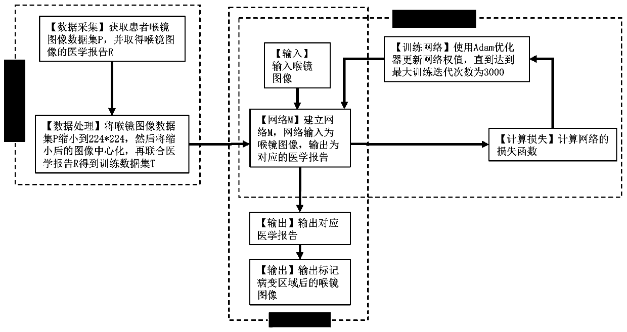
[0029] Reference figure 1 , The implementation steps of this example are as follows:

[0030] Step 1: Data preparation;

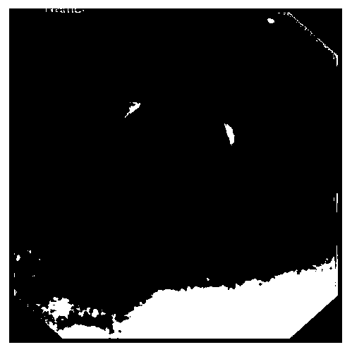
[0031] 1a) Obtain the laryngoscope image of the patient, record it as the laryngoscope data set P, and obtain the medical report of the laryngoscope image, record it as the label data set R; examples of the laryngoscope data set P are as follows figure 2 Shown

[0032] 1b) Obtain the training data set T:

[0033] 1b1) Reduce each image in the laryngoscope data set P to 224*224;

[0034] 1b2) Centering each reduced image, that is, subtracting (104, 116, 122) from the pixel value of the reduced image to obtain the pixel value (x', y', z') of the centered image:

[0035] (x',y',z')=(x-104,y-116,z-122)

[0036] Among them, (x, y, z) is the pixel value of the original image;

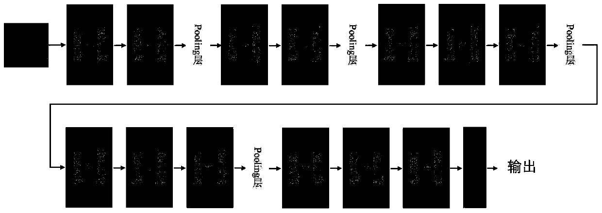
[0037] 1b3) After the laryngoscope ...


PUM


Abstract

The invention discloses an attention mechanism-based optical laryngoscope image lesion area labeling method, and mainly solves the problems that in the prior art, lesion area labeling is not performedon an optical laryngoscope image, and overfitting is easy to occur on a small data set. According to the implementation scheme, a laryngoscope image data set and an image data set label are obtained;scaling and centralizing the image data set, and marking the centralized image data set and the image data set label as a training data set; constructing an 18-layer network, taking the training dataset as training data of the network, and optimizing the network by using an adaptive learning rate optimization algorithm to obtain a trained network; and inputting a laryngoscope image into the trained network, obtaining a corresponding lesion area in the label data set according to the generated report, and labeling the lesion area. According to the method, overfitting of a small data set is avoided, the lesion area of the optical laryngoscope image can be obtained and marked, and a doctor can diagnose the optical laryngoscope image conveniently.

Description

Technical field [0001] The invention belongs to the field of image comprehension, and particularly relates to a method for marking a lesion area of ​​an optical laryngoscope image, which can be used for marking the lesion area of ​​an optical laryngoscope image, and improves the diagnosis efficiency and accuracy of the doctor on the optical laryngoscope image. Background technique [0002] Laryngoscope images play an important role in the diagnosis and treatment of diseases in the nasal cavity and throat. However, the diagnosis of laryngoscope images generally requires a professional doctor to carefully examine each area in the original image. This is a valuable tool for doctors. Challenging task. Because there is no suggestive annotation in the original image, all lesions can only be observed by the doctor's naked eye. Prolonged observation will cause the doctor's attention drop and mental fatigue, which will lead to the doctor's missed and misjudged and diagnostic efficiency du...

Claims


Application Information

Patent Timeline
IPC IPC(8): G06T7/00
CPCG06T7/0012G06T2207/20081G06T2207/20084G06T2207/30204
Inventor 缑水平李国栋谭瑶毛莎莎许成陈佳伟焦昶哲焦李成
Owner XIDIAN UNIV
Why Eureka
Try Eureka