
Knife gate for power system with pressurization prompt

A technology of power system and knife switch, which is applied in the direction of circuits, electric switches, electrical components, etc., can solve problems such as difficulty in judging, increasing current, and difficulty in seeing whether the knife switch is completely closed, etc., to achieve convenient judgment methods and avoid equipment Damage, easy to judge whether the switch is closed or not

Active Publication Date: 2019-12-24
SHANDONG LUNENG LIYUAN ELECTRIC EQUIP
View PDF14 Cites 0 Cited by
  • Summary
  • Abstract
  • Description
  • Claims
  • Application Information

AI Technical Summary

Problems solved by technology

[0002] The power system is an electric energy production and consumption system composed of power plants, power transmission and transformation lines, power supply and distribution stations, and electricity consumption. There is a switch called a switch in the equipment that consumes electricity, which is used to control the switch of the equipment circuit. , the current knife switch is not easy to see whether it is fully closed when it is closed, it is difficult to judge, and because it is not sure whether it is closed, if it is not fully closed, it is easy to cause a sudden increase in current, causing equipment to burn out and affecting The production of the equipment, and may cause harm to the equipment operators, especially the installation position of the knife switch is relatively remote, the light is relatively dim, and it is difficult to see clearly, so specific criteria are needed to determine whether the switch is closed, so we propose an enhanced The power system with pressure prompt uses a knife switch to solve the above problems

Method used


Image

  • Knife gate for power system with pressurization prompt
  • Knife gate for power system with pressurization prompt
  • Knife gate for power system with pressurization prompt

Examples


Embodiment Construction

[0016] The following will clearly and completely describe the technical solutions in the embodiments of the present invention with reference to the accompanying drawings in the embodiments of the present invention. Obviously, the described embodiments are only some, not all, embodiments of the present invention. Based on the embodiments of the present invention, all other embodiments obtained by persons of ordinary skill in the art without making creative efforts belong to the protection scope of the present invention.

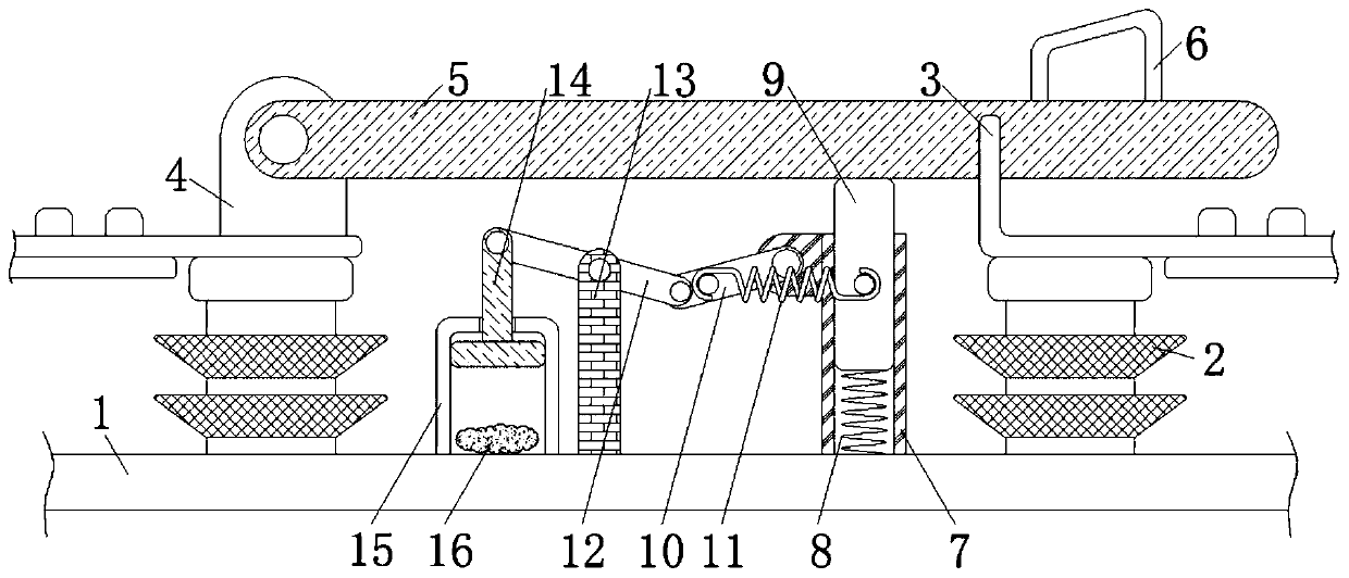
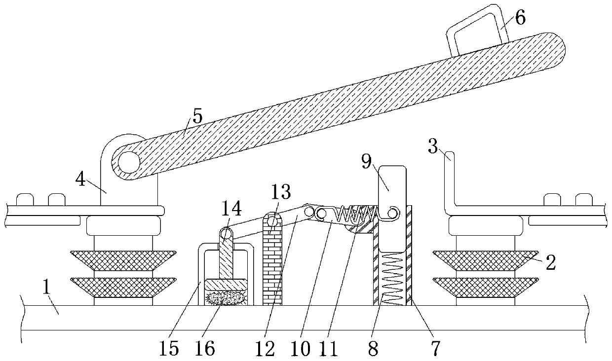
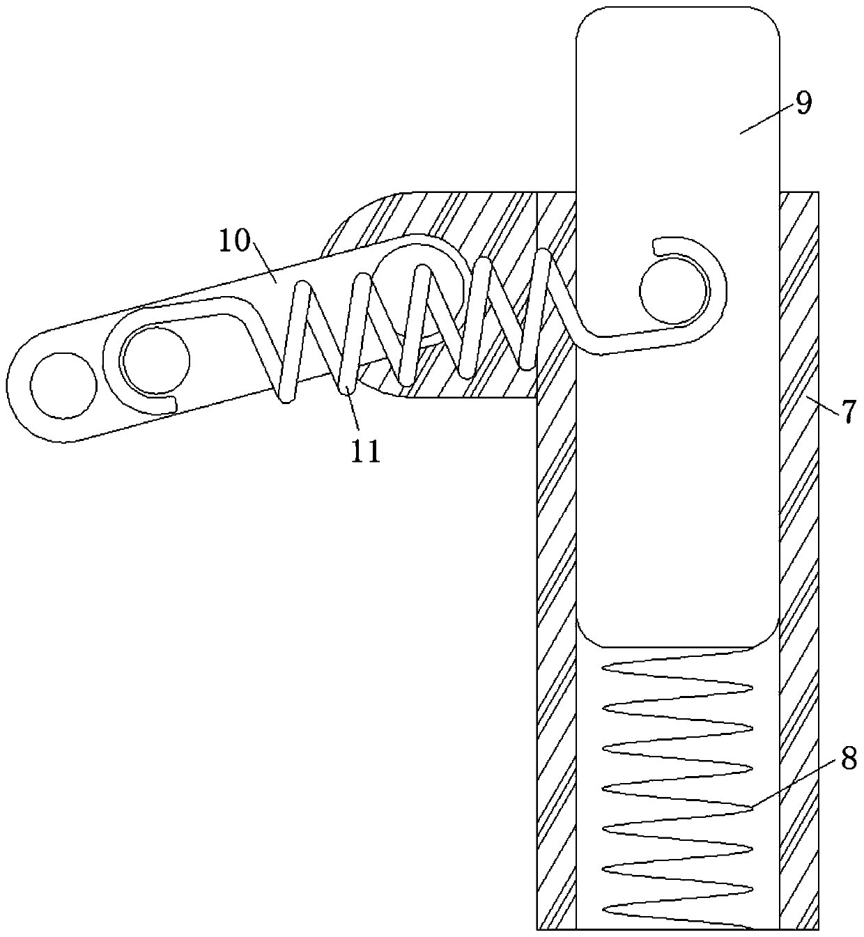
[0017] see Figure 1-3 , a knife switch for a pressurized power system, including a base 1, the base 1 plays a supporting role, the material of the base 1 is an insulating hard plastic material and the shape of the base 1 is a cuboid, and the role of the insulator 2 is to play Electrical insulation and mechanical fixation, both sides of the top of base 1 are fixedly connected with insulator 2, and the top of right insulator 2 is fixedly connected with static c...


PUM


Abstract

The invention relates to a knife gate for a power system with pressurization prompt. The knife gate comprises a base. Insulators are fixedly connected with both sides of the top of the base. Accordingto the knife gate for the power system with pressurization prompt, a piston and a light-emitting block are used together; when the knife blade is not closed, the piston moves downward under the action of a lever; the piston compresses the air in a prompt tube, which is equivalent to pressurize more air; the temperature of the pressurized air rises; after the temperature in the prompt tube rises,the light-emitting block absorbs heat and conduct the heat to rare earth phosphor on the surface; the rare earth phosphor emits light after being heated; after the knife blade is closed, the piston rises, and no longer pressurizes the air in the prompt tube; at the moment, the heat of the air is reduced, and the rare earth phosphor on the surface of the light-emitting block no longer emits light;according to whether the light-emitting block emits light, the state of the knife blade is judged; and whether the knife blade is closed is conveniently determined, which prevents equipment from beingdamaged.

Description

technical field [0001] The invention relates to the technical field of knife switches, in particular to a knife switch for a power system with pressurized prompts. Background technique [0002] The power system is an electric energy production and consumption system composed of power plants, power transmission and transformation lines, power supply and distribution stations, and electricity consumption. There is a switch called a switch in the equipment that consumes electricity, which is used to control the switch of the equipment circuit. , the current knife switch is not easy to see whether it is fully closed when it is closed, it is difficult to judge, and because it is not sure whether it is closed, if it is not fully closed, it is easy to cause a sudden increase in current, causing equipment to burn out and affecting The production of the equipment, and may cause harm to the equipment operators, especially the installation position of the knife switch is relatively rem...

Claims


Application Information

Patent Timeline
Patent Type & Authority Applications(China)
IPC IPC(8): H01H9/16H01H21/02
CPCH01H9/161H01H21/025
Inventor 徐海军
Owner SHANDONG LUNENG LIYUAN ELECTRIC EQUIP
Learn More