Connector assembly and tail attachment thereof

A technology of connector components and tail accessories, which is applied to the parts, connections, electrical components, etc. of the connection device, can solve the problems that it is difficult to ensure the stability and fixation of the plastic package and affect the quality of the product, and achieve the goal of ensuring stable fixation and product quality Effect

Inactive Publication Date: 2019-12-24
CHINA AVIATION OPTICAL-ELECTRICAL TECH CO LTD
View PDF5 Cites 0 Cited by
  • Summary
  • Abstract
  • Description
  • Claims
  • Application Information

AI Technical Summary

Problems solved by technology

[0004] The purpose of the present invention is to provide a connector assembly to solve the problem that in the prior art, when the plastic package is subjected to a force along the circumferential direction of the tail attachment, it is difficult to ensure that the plastic package only depends on the adhesive force between the plastic package and the tail attachment. Stable fixation on the tail attachment causes the plastic package to rotate relative to the tail attachment, which affects product quality; the purpose of the present invention is also to provide a tail attachment to solve the problem that the plastic package in the prior art is subjected to force along the circumference of the tail attachment. When the force is applied, it is difficult to ensure the stable fixation of the plastic package on the tail accessory only by relying on the adhesive force between the plastic package and the tail accessory, which will cause the plastic package to rotate relative to the tail accessory and affect the quality of the product

Method used


Image

  • Connector assembly and tail attachment thereof
  • Connector assembly and tail attachment thereof
  • Connector assembly and tail attachment thereof

Examples


Embodiment Construction

[0024] Embodiments of the present invention will be further described below in conjunction with the accompanying drawings.

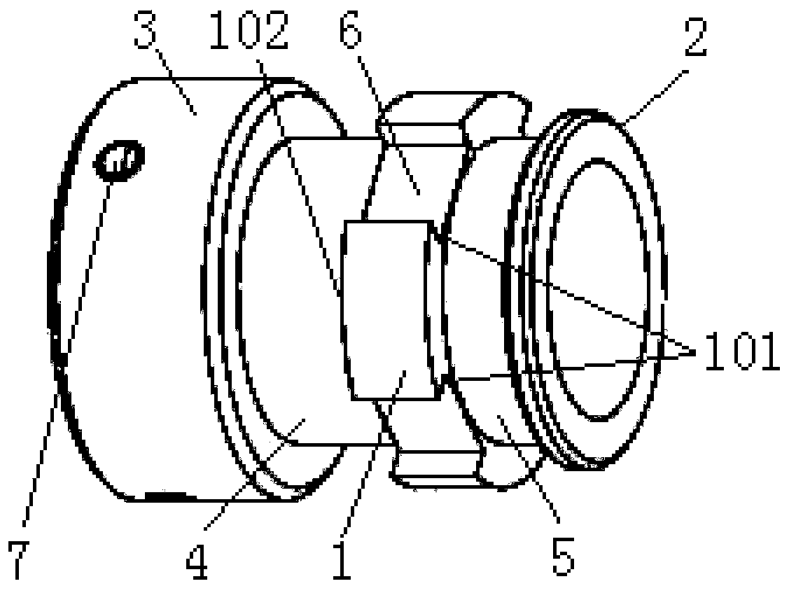
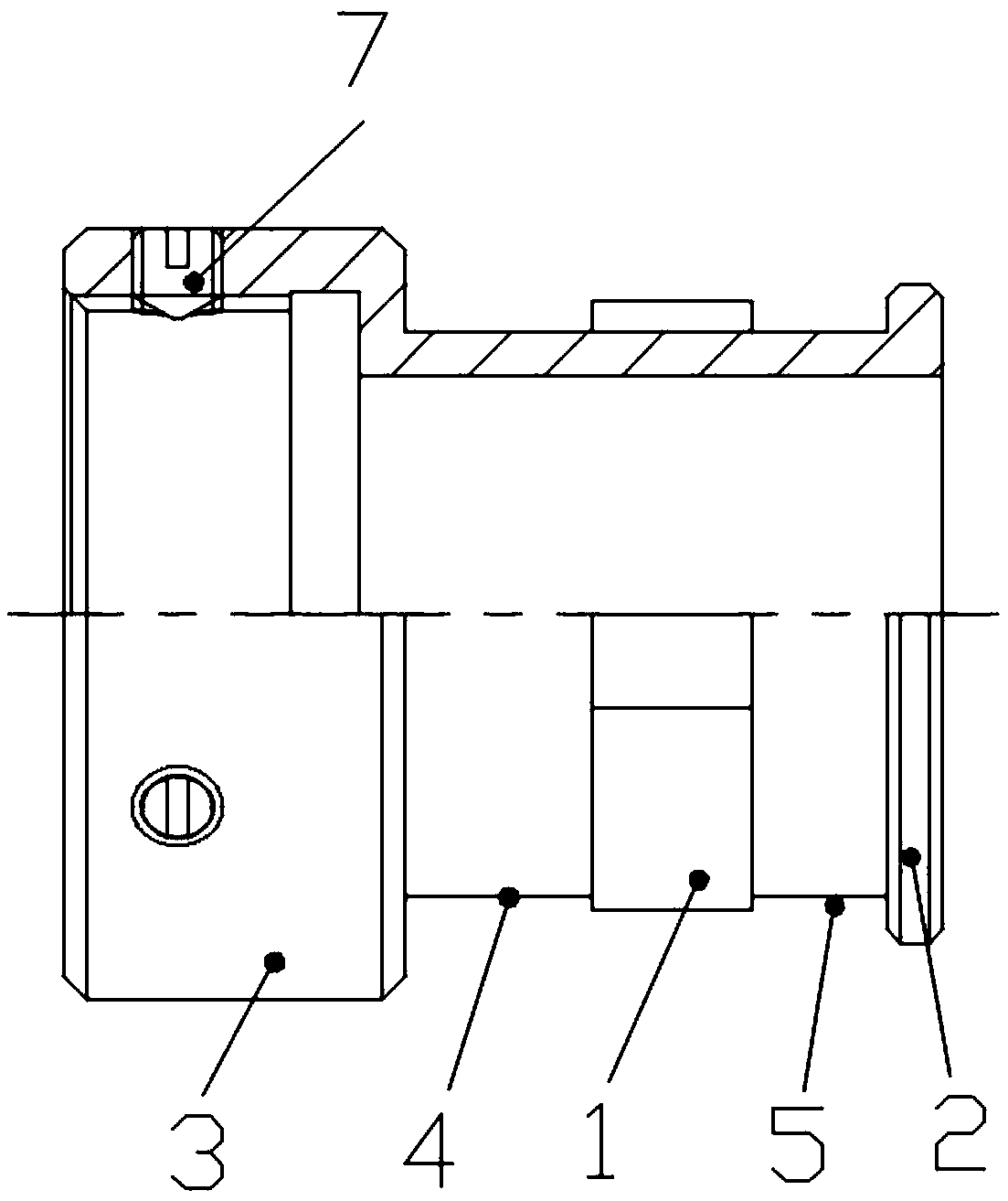
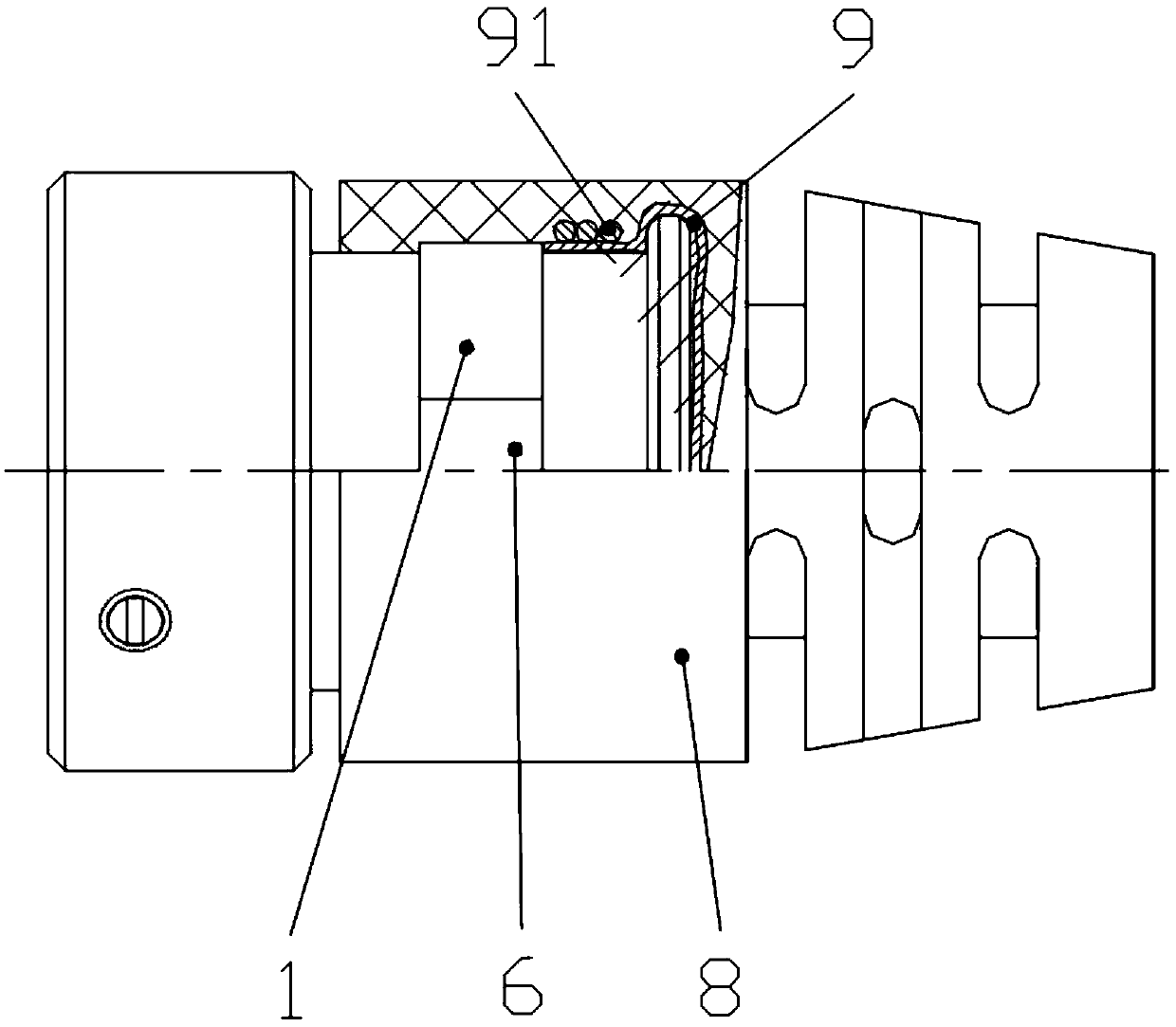
[0025] Specific embodiment 1 of the tail attachment of the present invention, such as figure 1 and figure 2 As shown, the end of the tail attachment for fixed connection with the connector is defined as the front end of the tail attachment, and the tail attachment includes a connecting part 3 arranged from front to back for fixed connection with the connector and a plastic seal for mating The fixed section of the plastic package. The connecting part 3 is provided with an internal thread fixedly connected with the connector. The connecting part 3 is also provided with a threaded hole extending in the radial direction of the tail attachment. Top wire 7 on the connector. Four projections 1 are arranged at intervals along the circumferential direction on the outer periphery of the fixed section of the plastic package, and a ring of projections 1 is provi...


PUM


Abstract

The invention relates to a connector assembly and a tail attachment thereof. The connector assembly comprises a connector and the tail attachment which is fixedly connected with the rear end of the connector. The tail attachment is provided with a plastic sealing body fixing section for cooperating with a plastic sealing body. The plastic sealing body fixing section is provided with an anti-rotation groove in circumferential rotation prevention cooperation with the plastic sealing body. The anti-rotation groove comprises two circumferential stop surfaces which are oppositely arranged along thecircumferential direction of the tail attachment to realize stop cooperation with the plastic sealing body. When the plastic sealing body is subjected to circumferential force, the plastic sealing body is mainly limited by the stop effect of the anti-rotation groove. Stability and fixation of the plastic sealing body on the tail attachment can be effectively guaranteed, thereby ensuring the product quality. The problem that when the plastic sealing body is subjected to the force in the circumferential direction of the tail attachment, stability and fixation of the plastic sealing body on thetail attachment are difficultly ensured only through the adhesive force between the plastic sealing body and the tail attachment, and the plastic sealing body rotates relative to the tail attachment and affects the product quality is solved.

Description

technical field [0001] The present invention relates to connector assemblies and tail attachments thereof. Background technique [0002] At present, plastic sealing products at the tail of the connector usually adopt the method of processing grooves on the tail attachment to increase the tensile effect of the plastic. The authorized announcement number is CN206274563U, and the Chinese utility model patent whose authorized announcement date is 2017.06.23 discloses a connector and its tail attachment structure that improves the shielding process structure. It includes a connector and a tail attachment. The connector includes The connector body and the rear end of the connector body are connected with a connector thread, and a connector gear ring is arranged inside the connector thread, and the connector gear ring is tightly matched with the inner cavity of the connector thread; The tail attachment includes a tail attachment thread, the middle part of the inner cavity of the t...

Claims


Application Information

Patent Timeline
IPC IPC(8): H01R13/504
CPCH01R13/504
Inventor 万宁
Owner CHINA AVIATION OPTICAL-ELECTRICAL TECH CO LTD
Why Eureka
Try Eureka