Telescopic supporting leg and crane

A technology of telescopic outriggers and outrigger boxes, which is applied in cranes, transportation and packaging, and can solve problems such as deformation of the piston rod of the horizontal oil cylinder 2, scrapping of the horizontal oil cylinder 2, and affecting the overall work of the telescopic outriggers, so as to reduce the probability of damage, Make sure it works

Pending Publication Date: 2019-12-27
SANY AUTOMOBILE HOISTING MACHINERY
View PDF0 Cites 0 Cited by
  • Summary
  • Abstract
  • Description
  • Claims
  • Application Information

AI Technical Summary

Problems solved by technology

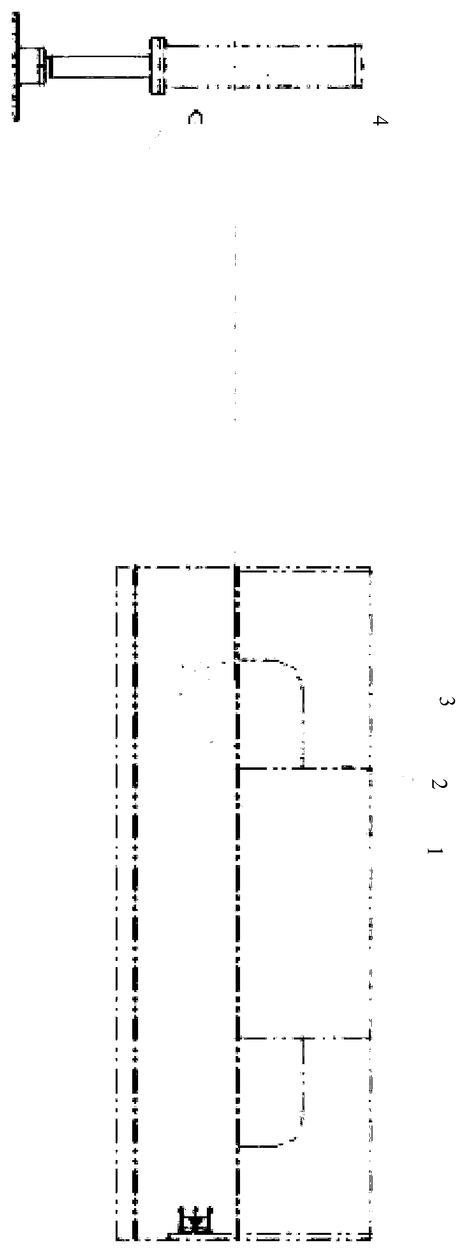
[0004] However, in this structure, the horizontal oil cylinder 2 is both an action actuator and a support mechanism. In the case of the existing movable outrigger 3 running sideways or deforming, it is easy to cause deformation of the piston rod of the horizontal oil cylinder 2, resulting in the direct scrapping of the horizontal oil cylinder 2 , thus affecting the overall work of the telescopic outriggers

Method used


Image

  • Telescopic supporting leg and crane
  • Telescopic supporting leg and crane
  • Telescopic supporting leg and crane

Examples


Embodiment Construction

[0029] In order to make the purposes, technical solutions and advantages of the embodiments of the present invention clearer, the technical solutions in the embodiments of the present invention will be clearly and completely described below with reference to the accompanying drawings in the embodiments of the present invention. Obviously, the described embodiments These are some embodiments of the present invention, but not all embodiments. The components of the embodiments of the invention generally described and illustrated in the drawings herein may be arranged and designed in a variety of different configurations.

[0030] Thus, the following detailed description of the embodiments of the invention provided in the accompanying drawings is not intended to limit the scope of the invention as claimed, but is merely representative of selected embodiments of the invention. Based on the embodiments of the present invention, all other embodiments obtained by those of ordinary ski...


PUM


Abstract

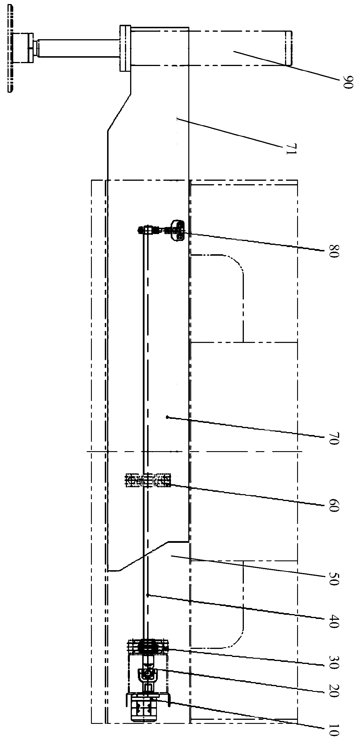
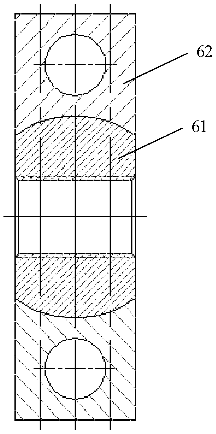
The invention provides a telescopic supporting leg and a crane, and belongs to the technical field of movable supporting legs. The telescopic supporting leg comprises a supporting leg box, a movable supporting leg, a telescopic structure and a driving piece. The movable supporting leg is sleeved with the supporting leg box. One end of the telescopic structure is in transmission connection with thedriving piece. The other end of the telescopic structure is connected with the movable supporting leg. The telescopic structure is used for making the movable supporting leg do telescopic movements relative to the supporting leg box. The driving piece serves as a driving action actuating element of the telescopic supporting leg. The telescopic structure serves as a supporting element for supporting the supporting leg box and the movable supporting leg and bearing the loads exerted on the supporting leg box and the movable supporting leg by the outside. By arranging the driving piece and the telescopic structure independently, the driving piece does not need to bear the loads of the movable supporting legs, the deformation and deviation of the movable supporting legs have no influences onthe driving piece, the damage rate of the driving piece is reduced, and the normal work of the telescopic supporting leg is ensured.

Description

technical field [0001] The invention relates to the technical field of movable outriggers, in particular to a telescopic outrigger and a crane. Background technique [0002] Outriggers are the most commonly used structures on construction machinery and equipment, which are used to support mechanical equipment and stabilize the mechanical equipment for engineering operations. In order to facilitate the operation, the outriggers are generally retractable structures. [0003] Existing telescopic outriggers such as figure 1 As shown, the structure of a telescopic arm is generally adopted, and one end of the horizontal oil cylinder 2 is fixed in the fixed outrigger box 1, and the piston rod of the horizontal oil cylinder 2 is connected with the existing movable outrigger 3. The legs 3 are extended and retracted along the fixed outrigger box 1, and the existing vertical oil cylinder 4 is used to provide the power to support the mechanical equipment. [0004] However, in this st...

Claims


Application Information

Patent Timeline
IPC IPC(8): B66C23/80
CPCB66C23/80B66C2700/0378
Inventor 刘志平张志敏李行
Owner SANY AUTOMOBILE HOISTING MACHINERY
Why Eureka
Try Eureka