Spindle storing and pushing device

A technology of pushing device and spindle, applied in the field of spindle storage and pushing device, can solve the problems of easy chain slack, huge labor cost, downgrading of spindle, etc., and achieve the effect of avoiding screw failure, alleviating work intensity and ensuring product quality.

Pending Publication Date: 2019-12-31
WUXI HONGYUAN ELECTROMECHANICAL TECH
View PDF0 Cites 0 Cited by
  • Summary
  • Abstract
  • Description
  • Claims
  • Application Information

AI Technical Summary

Problems solved by technology

[0002] In the prior art, since the spinning production line of textile machinery generally has a large number of stations, when producing spindles, the time interval for full winding is short, and the spindle transfer vehicles are usually too late to adapt to the rhythm of the entire production line
[0003] Secondly, the lifting and handling of spindle products is usually carried out by manpower. Each spindle weighs about 15kg, and it is carried thousands of times per person per day by manpower, which consumes a lot of labor.
And in the process of manual handling, once the end face of the spindle is touched, it is very easy to cause the spindle to be downgraded, resulting in economic losses
[0004] At the same time, the traditional spindle storage and pushing device adopts the cylinder transmission structure, which occupies a large space and requires additional air sources and air pipes in the workshop.
In addition, the transmission length of the cylinder is close to twice the length of the cylinder itself, which takes up a lot of space. For some users with limited workshop space, this method is not suitable.
[0005] In addition, the traditional spindle storage and pushing device also adopts the chain transmission method, which is easy to wrap waste silk on the surface of the chain during movement, and needs to be cleaned frequently, which not only affects the product quality, but also easily causes chain failure. It must be checked and repaired frequently. security is not stable
At the same time, the chain is easy to relax during long-term operation, and the chain needs to be tensioned regularly. This method greatly affects the production efficiency of the automated production workshop

Method used


Image

  • Spindle storing and pushing device
  • Spindle storing and pushing device

Examples


Embodiment Construction

[0023] The technical solution of the present invention will be further described below in conjunction with the accompanying drawings.

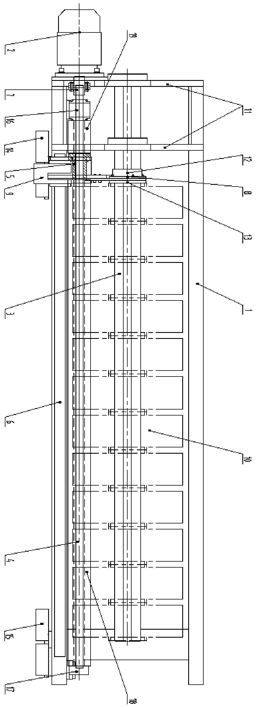
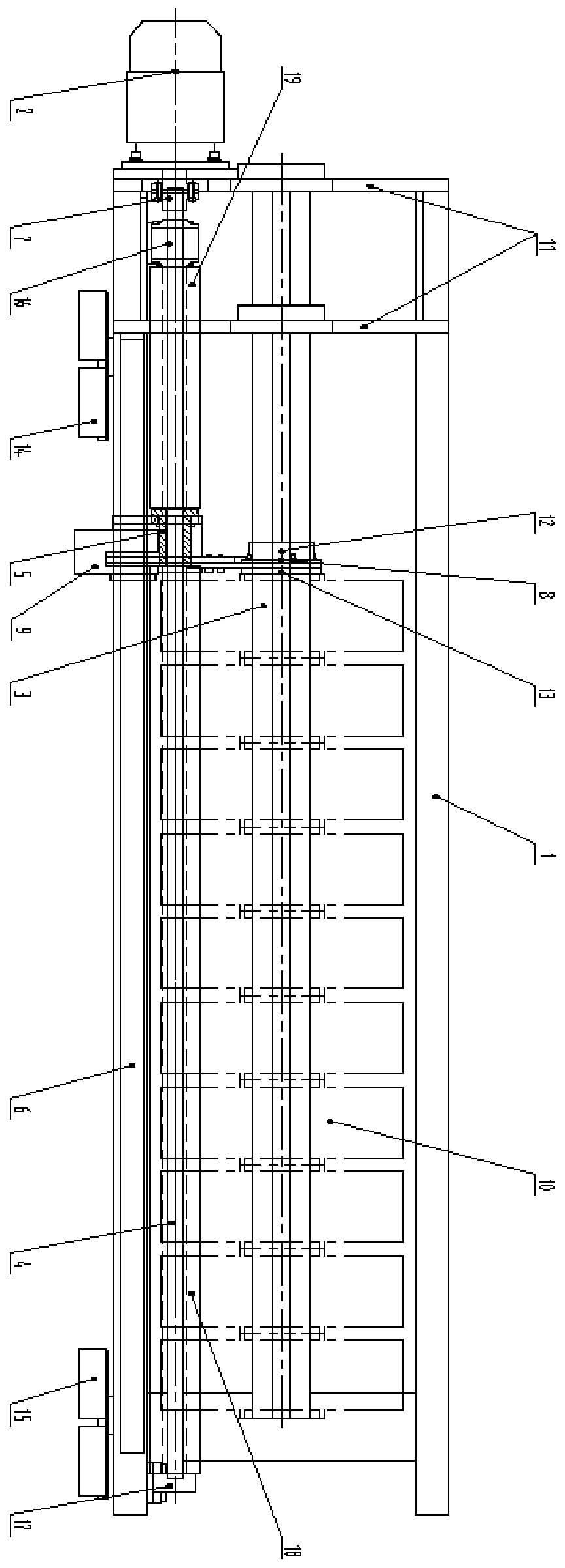
[0024] refer to Figure 1 ~ Figure 2 , which are respectively a structural schematic diagram of a spindle storage and pushing device provided in an embodiment of the present invention when storing a spindle, and a structural schematic diagram of a spindle storage and pushing device provided in an embodiment of the present invention when pushing a spindle, including various components, A detailed description will be given below in conjunction with the accompanying drawings.

[0025] In the embodiment of the present invention, the spindle storage and pushing device includes: a frame 1, a spindle hanging shaft 3, a push arm device 8, a lead screw 4, a lead screw nut 5 and a drive motor 2, wherein: the frame 1 includes The frame support plate 11 for hanging other components through the hanging hole; the spindle hanging shaft 3 is hung on the fram...


PUM


Abstract

The invention discloses a spindle storing and pushing device. The spindle storing and pushing device comprises a frame, a spindle hanging shaft, a pushing arm device, a screw, a screw nut and a drivemotor, wherein the frame includes frame supporting plates used for hanging other assemblies through hanging holes; the spindle hanging shaft is hanged on the frame through the frame supporting plates,and is used for storing spindles; the pushing arm device is arranged on the spindle hanging shaft in a sleeving manner; the screw is hanged on the frame through the frame supporting plates, and the surface of the screw is provided with threads; the screw nut is arranged on the screw in a sleeving manner, is matched with the threads on the surface of the screw, and is connected with the pushing arm device; and the drive motor is connected with the screw, and is used for driving the screw to rotate, and when the screw rotates, the pushing arm device is driven by the screw nut to move along thespindle hanging shaft. By employing the scheme, spindles just produced can be hanged on the spindle hanging shaft, and the spindles are stored through the spindle hanging shaft, so that the operationstrength of a spindle transfer trolley is reduced; and the spindles hanged on the spindle hanging shaft can be pushed through the pushing arm device, so that manpower consumption is reduced.

Description

technical field [0001] The invention relates to the field of machinery, in particular to a spindle storage and pushing device. Background technique [0002] In the prior art, since the spinning production line of textile machinery generally has a large number of stations, when producing spindles, the time interval for full winding is short, and the spindle transfer vehicles are usually too late to adapt to the rhythm of the entire production line. [0003] Secondly, the lifting and handling of spindle products is usually carried out by manpower. Each spindle weighs about 15kg, and it is carried thousands of times per person per day by manpower, which consumes a lot of labor. And in the process of manual handling, once the end face of the spindle is touched, it is very easy to cause the spindle to downgrade and cause economic loss. [0004] At the same time, the traditional spindle storage and pushing device adopts a cylinder transmission structure, which occupies a large sp...

Claims


Application Information

Patent Timeline
Patent Type & Authority Applications(China)
IPC IPC(8): B65H49/38
CPCB65H49/38B65H2701/31
Inventor 钱怡君孙斌付光怀杨琴
Owner WUXI HONGYUAN ELECTROMECHANICAL TECH
Why Eureka
Try Eureka