
Automatic mechanical lifting tool

A spreader and machinery technology, applied in the field of automated mechanical spreaders, can solve problems such as poor stability and weak grasping, and achieve the effects of improving stability, reducing workload, and protecting internal structures

Inactive Publication Date: 2019-12-31
太仓木利机械科技有限公司
View PDF0 Cites 0 Cited by
  • Summary
  • Abstract
  • Description
  • Claims
  • Application Information

AI Technical Summary

Problems solved by technology

[0004] The purpose of the present invention is to provide an automatic mechanical spreader to solve the problems of poor stability and weak grasping in the above-mentioned background technology

Method used


Image

  • Automatic mechanical lifting tool
  • Automatic mechanical lifting tool
  • Automatic mechanical lifting tool

Examples


Embodiment Construction

[0019] The following will clearly and completely describe the technical solutions in the embodiments of the present invention with reference to the accompanying drawings in the embodiments of the present invention. Obviously, the described embodiments are only some, not all, embodiments of the present invention.

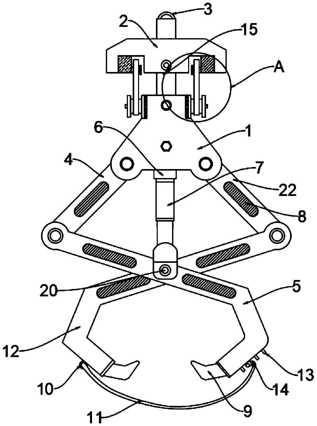
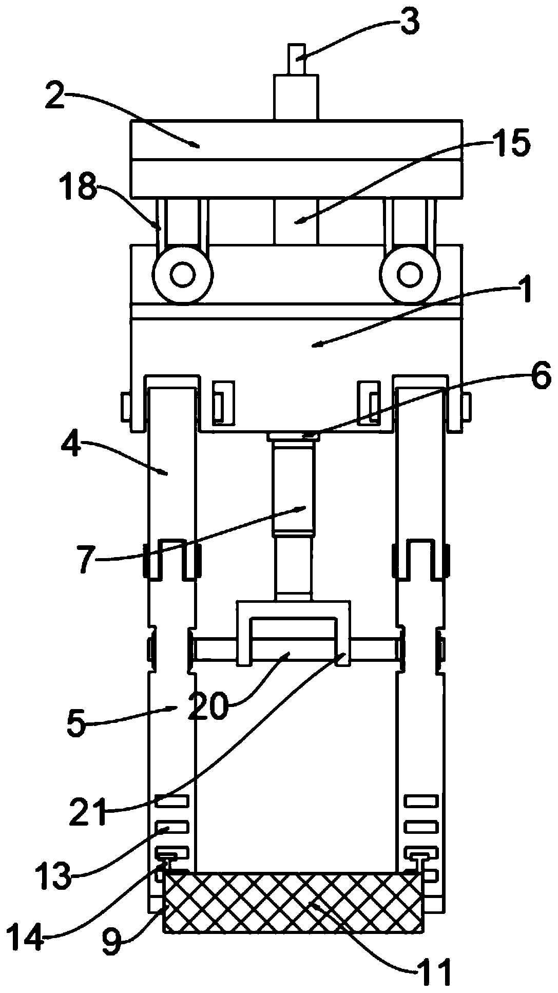
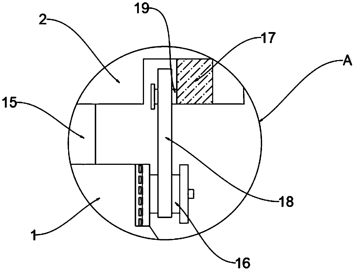
[0020] see Figure 1-3 , an embodiment provided by the present invention: an automatic mechanical spreader, including a spreader frame 1, the interior of the spreader frame 1 is respectively provided with a first oblique arm 4 and a second oblique arm 22, and the first oblique arm 4 Located on one side of the second oblique arm 22, the first tong arm 5 is installed below the first oblique arm 4, the side of the lower end of the first tong arm 5 is provided with a hook ring 13, and the second oblique arm 22 is installed below the second oblique arm. Two pincer arms 12, a net bag 11 is installed between the fixed ring 10 and the hook ring 13, the inside of the fixed ri...


PUM


Abstract

The invention discloses an automatic mechanical lifting tool, relates to the technical field of mechanical lifting tools. The invention aims to solve the problems that the existing stability is poor and the grabbing is not firm. A first inclined arm and a second inclined arm are arranged inside a lifting tool frame correspondingly, a first clamp arm is mounted below the first inclined arm, a hookring is arranged on one side of the lower end of the first clamp arm, a second clamp arm is mounted below the second inclined arm, a fixing ring is arranged on one side of the lower end of the secondclamp arm, a fixing base is arranged at the middle position of the bottom of the lifting tool frame, an air cylinder is mounted below the fixing base, a fixing frame is arranged below the air cylinder, a connecting shaft is arranged at the lower end of the fixing frame, locking pins are arranged on the two sides of the upper end of the lifting tool frame, lifting rods are arranged at the upper part of the lifting tool frame, a lifting plate is arranged at the upper part of the lifting rods, buffering blocks are arranged on the two sides of the interior of the lifting plate, connecting rods arearranged outside movable shafts.

Description

technical field [0001] The invention relates to the technical field of mechanical slings, in particular to an automatic mechanical sling. Background technique [0002] Spreader refers to the device for lifting heavy objects in hoisting machinery. The most commonly used lifting tools for lifting items are hooks and slings, and others include rings, lifting suction cups, clamps and forks. It is widely used in the lifting and hoisting industry. Lifting suction cups, clamps and forks can be used as special spreaders on the crane for a long time, and can also be used as replaceable auxiliary spreaders on the hook for temporary use. They are often used in Multi-species warehouses and yards to improve operational efficiency. [0003] However, the existing mechanical spreader will shake when lifting the object. Since the hanger rod is connected with the spreader frame, the shake will be transmitted downward with the spreader frame, resulting in poor stability and long-term shaking...

Claims


Application Information

Patent Timeline
Patent Type & Authority Applications(China)
IPC IPC(8): B66C1/10
CPCB66C1/10
Inventor 王芒利李莉杨盛涵杨兵
Owner 太仓木利机械科技有限公司
Learn More