Triggering automatic locking structure

A technology of automatic locking and structural parts, which is applied in the direction of building locks, building construction, construction, etc., and can solve problems such as troubles

Inactive Publication Date: 2019-12-31
李川涛
View PDF0 Cites 4 Cited by
  • Summary
  • Abstract
  • Description
  • Claims
  • Application Information

AI Technical Summary

Problems solved by technology

[0003] The existing mechanical locks, smart locks, and locking functions are all done manually. One structure is to lift the armrest after closing the door, and drive the non-automatic deadbolt into the door frame to realize the locking function. The other structure is to insert The key reversely turns the lock cylinder to drive the non-automatic deadbolt into the door frame to realize the locking function. Both structures require human manipulation, which is troublesome. Therefore, it is necessary to find a lock that does not require human manipulation and can automatically complete the locking function. The structure, the structure that realizes the automatic locking function

Method used


Image

  • Triggering automatic locking structure
  • Triggering automatic locking structure
  • Triggering automatic locking structure

Examples


Embodiment Construction

[0020] The present invention will be further described below in conjunction with the accompanying drawings, but the content of the present invention is not limited thereto.

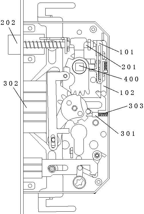
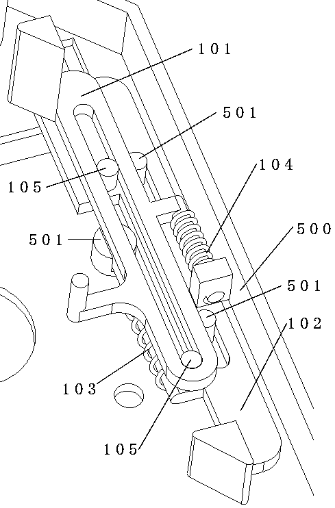
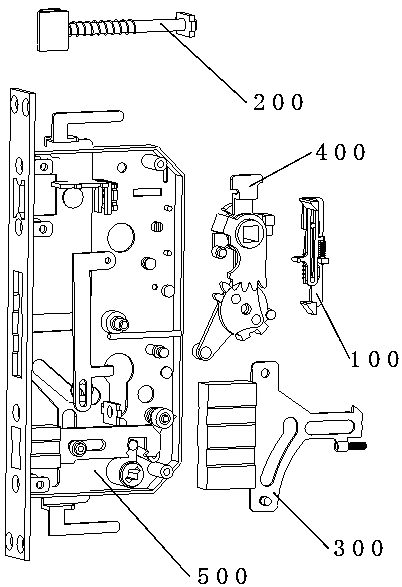
[0021] figure 1 Among them, the lock position trigger structure (100) is installed on the lock body, the trigger structure part (101) of the lock position trigger structure (100) is kinematically connected with the dead bolt rod (201) of the self-retracting dead bolt structure (200), and the lock position The locking structural part (102) of the triggering structure (100) is kinematically connected with the deadbolt frame (301) of the non-self-retracting deadbolt structure (300), and the triggering structural part (101) of the locking triggering structure (100) is connected with the lock The tongue telescopic drive structure (400) is kinematically connected. When unlocking, the bolt telescopic drive structure (400) drives the self-retracting bolt structure (200), the non-self-retracting bolt structure (3...


PUM


Abstract

The invention discloses a triggering automatic locking structure. Through a function that a self-retraction spring bolt retracts after touching a doorframe during door closing, when retracting, the self-retraction spring bolt triggers a locking position triggering mechanism, thus during unlocking, a non-self-retraction spring bolt retracting to be clamped by the locking position triggering structure under manual driving extends forwards automatically into a doorframe spring bolt groove, and a triggering automatic locking function is achieved.

Description

technical field [0001] The invention relates to mechanical locks, mechanical lock bodies, intelligent locks, intelligent lock bodies and other related fields. [0002] technical background [0003] The existing mechanical locks, smart locks, and locking functions are all done manually. One structure is to lift the armrest after closing the door, and drive the non-automatic deadbolt into the door frame to realize the locking function. The other structure is to insert The key reversely turns the lock cylinder to drive the non-automatic deadbolt into the door frame to realize the locking function. Both structures require human manipulation, which is troublesome. Therefore, it is necessary to find a lock that does not require human manipulation and can automatically complete the locking function. The structure realizes the structure of automatic locking function. Contents of the invention [0004] The purpose of the present invention is to provide a trigger automatic locking...

Claims


Application Information

Patent Timeline
Patent Type & Authority Applications(China)
IPC IPC(8): E05B63/14E05B15/10
CPCE05B15/101E05B63/146
Inventor 李川涛
Owner 李川涛
Why Eureka
Try Eureka