High-voltage incoming cabinet with self-locking function and working method of high-voltage incoming cabinet

A technology for high-voltage incoming lines and incoming cabinets, which is applied in the direction of pull-out switchgear, switchgear, electrical components, etc., which can solve problems such as personal injury and easy accidental touch by operators, so as to prevent loss of position, improve safety, Guaranteed coverage

Pending Publication Date:
View PDF0 Cites 0 Cited by
  • Summary
  • Abstract
  • Description
  • Claims
  • Application Information

AI Technical Summary

Problems solved by technology

When the handcart exits, the high-voltage equipment in the high-voltage incoming cabinet is exposed, and the operator is easy to accidentally touch it, which may cause personal injury

Method used


Image

  • High-voltage incoming cabinet with self-locking function and working method of high-voltage incoming cabinet

Examples


Embodiment 1

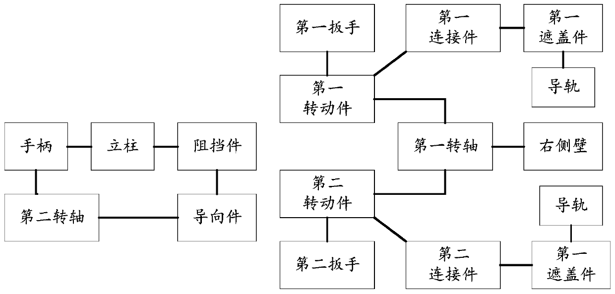
[0036] figure 1 Schematically gives a simplified structural diagram of the high-voltage incoming line cabinet with self-locking function according to the embodiment of the present invention, as shown in figure 1 As shown, the high-voltage incoming line cabinet includes:

[0037] a circuit breaker chamber having a rear side wall, a left side wall, and a right side wall;

[0038] a first contact group and a second contact group, the second contact group and the first contact group are arranged on the rear side wall from top to bottom;

[0039] The first cover and the second cover are rectangular sheet structures, the first cover is used to cover the first contact group, and the left and right sides of the first cover are respectively arranged on the guide rail; The second cover is used to cover the second contact group, and the left and right sides of the second cover are respectively arranged on the guide rail; the first cover and the second cover move up and down on the guid...

Embodiment 2

[0068] An application example of a high-voltage incoming cabinet with a self-locking function according to an embodiment of the present invention.

[0069] In this application example, in the vertical direction, the first wrench, the handle and the second wrench are set up and down in sequence; a guide is set to convert the rotation of the handle into the back and forth movement of the blocking piece. When the handle is pushed by an external force such as a handcart, The stopper is out of position to realize the automatic opening function; under the action of the withdrawal of the handcart and the spring, the stopper returns to the position to realize the automatic locking function; the left and right sides of the first cover and the second cover have connecting parts , the cylindrical guide rail passes through the connecting part to realize the up and down movement of the covering part, and the section of the connecting part on the horizontal plane is "]" shaped; the first rot...


PUM


Abstract

The invention provides a high-voltage incoming cabinet with a self-locking function and a working method of the high-voltage incoming cabinet. The high-voltage incoming cabinet comprises a circuit breaker chamber; the interior of the circuit breaker chamber is provided with a rear side wall, a left side wall and a right side wall, wherein the rear side wall is provided with a second contact groupand a first contact group disposed sequentially along a vertical direction; the high-voltage incoming cabinet further comprises a covering component, a limiting component, a first assembly and a second assembly; the first assembly includes a first rotating component, a second rotating component, a first connecting component, a second connecting component, a first wrench, a second wrench, a blocking component, a handle, a spring and a torsion spring; one end of the spring is fixed, and the other end of the spring is disposed on the handle; the connecting point of the spring and the handle and the operating portion of the handle are respectively located at two sides of a second rotating shaft; the first rotating component is connected with the torsion spring; and the torsion spring sleeves afirst rotating shaft. The high-voltage incoming cabinet of the invention has the advantages of simple structure, reliable work, good protection effect and the like.

Description

technical field [0001] The invention relates to a high-voltage wire inlet cabinet, in particular to a high-voltage wire inlet cabinet with an automatic covering function and a working method thereof. Background technique [0002] At present, the basic structure of the high-voltage incoming line cabinet is: cabinet, handcart, and the grounding of the handcart is through the fixed cabinet. When the handcart enters and pulls out of the cabinet, the grounding device of the cart and the grounding of the handcart Device mating, disengagement. When the handcart exits, the high-voltage equipment in the high-voltage incoming cabinet is exposed, and the operator is easy to touch it by mistake, which may cause personal injury. Contents of the invention [0003] In order to solve the shortcomings in the above-mentioned prior art solutions, the present invention provides a high-voltage incoming cabinet with a self-locking function that has good safety performance and reliable operatio...

Claims


Application Information

Patent Timeline
Patent Type & Authority Applications(China)
IPC IPC(8): H02B1/30H02B11/133H02B11/04
Inventor 刘朝振聂建圣殷丽华谢群叶佳佳洪方慧
Why Eureka
Try Eureka