Baffle device achieving automatic locking

A baffle device, automatic technology, applied in manipulators, program-controlled manipulators, manufacturing tools, etc., can solve the problems of leg injury, difficulty in wearing exoskeleton products, etc., and achieve the effect of simple switching

Pending Publication Date: 2018-11-16
HANGZHOU ROBOCT TECH DEV CO LTD
View PDF5 Cites 0 Cited by
  • Summary
  • Abstract
  • Description
  • Claims
  • Application Information

AI Technical Summary

Problems solved by technology

[0002] The exoskeleton robot described in the present invention refers to a device that assists paraplegic or inconvenient walking wearers to walk. Generally, the wearer needs to be fixed on the exoskeleton robot with straps, and the leg straps are the force on the entire device. The largest part, the exoskeleton robot products currently on the market for medical assistance will increase the rigid baffle

Method used


Image

  • Baffle device achieving automatic locking
  • Baffle device achieving automatic locking
  • Baffle device achieving automatic locking

Examples


Embodiment Construction

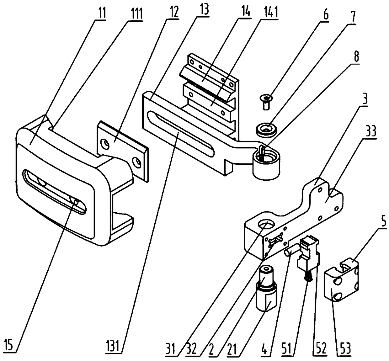
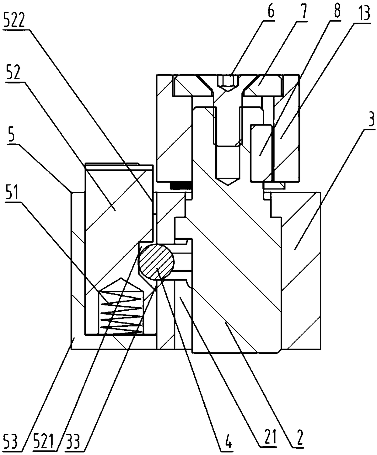
[0031] Such as Figure 1-5 As shown, it is an embodiment of a self-locking baffle device of the present invention, including a baffle 1, a rotating shaft 2, a fixing frame 3, a locking member 4 and a manipulation part 5; the fixing frame 3 is fixed on the exoskeleton robot At a designated position, a shaft hole 31 corresponding to the shaft 2 is opened on the fixed frame 3, and the shaft 2 passes through the shaft hole 31 and is fixedly connected with the baffle plate 1; There is a locking hole 32 vertically intersecting the shaft hole 31, corresponding to the position of the locking hole 32, a locking groove 21 is opened on the shaft 2; the operating part 5 includes an elastic part 51 and a The pressing block 52 at the free end of the elastic member 51; corresponding to the position of the locking hole 32, the pressing block 52 is provided with a groove 521 or a protrusion, the locking hole 32, the locking groove 21, The shape of the groove 521 matches the shape of the locki...


PUM


Abstract

A baffle device achieving automatic locking comprises a baffle, a rotating shaft, a fixed frame, a locking part and a control component. A rotating shaft hole corresponding to the rotating shaft is formed on the fixed frame. The rotating shaft penetrates through the rotating shaft hole to be fixedly connected with the baffle. A locking hole perpendicularly crossing with the rotating shaft hole isformed on the fixed frame, and a locking groove is formed at the position, corresponding to the locking hole, of the rotating shaft. The control component comprises an elastic component and a pressingblock arranged at the free end of the elastic component. The shape of the locking hole and the shape of the locking groove are matched with the shape of the locking part. When the elastic component is in an energy storage state, a groove or a boss is arranged at the position, corresponding to the locking hole, of the pressing block, the locking part is located in the groove and the locking hole or located in the locking hole, and the rotating shaft can drive the baffle to rotate. When the elastic component is automatically converted into an energy release state from the energy storage state,the locking part is clamped in the locking hole and the locking groove, the rotating shaft is automatically locked, the baffle is fixed in front of the knee of a human body, and the function of increasing the supporting strength of the leg is achieved.

Description

technical field [0001] The invention relates to an automatic locking baffle device, which belongs to the field of human body auxiliary medical devices, in particular to an automatic locking baffle device used for the legs of an exoskeleton robot. Background technique [0002] The exoskeleton robot described in the present invention refers to a device that assists paraplegic or inconvenient walking wearers to walk. Generally, the wearer needs to be fixed on the exoskeleton robot with straps, and the leg straps are the force on the entire device. The largest part, the exoskeleton robot products currently on the market for medical assistance will increase the rigid baffle device to increase the support strength of the legs, but the rigid baffle device is generally screwed or bolted to the equipment, which will affect the Wearing the exoskeleton product causes certain difficulties for the wearer; moreover, the wearer generally wears the exoskeleton from a sitting position. Durin...

Claims


Application Information

Patent Timeline
IPC IPC(8): B25J9/00B25J19/00
CPCB25J9/0006B25J19/00
Inventor 王天
Owner HANGZHOU ROBOCT TECH DEV CO LTD
Why Eureka
Try Eureka