
Sliding door device

A technology of sliding device and sliding door, which is applied in door/window fittings, building, wing leaf control mechanism, etc. It can solve the problems of troublesome operation, door weight, occupancy, etc., and achieve the effect of convenient operation and simple structure

Inactive Publication Date: 2018-12-28
屠建松
View PDF0 Cites 0 Cited by
  • Summary
  • Abstract
  • Description
  • Claims
  • Application Information

AI Technical Summary

Problems solved by technology

[0002] At present, the sliding doors on the market are mainly straight rail sliding doors. The door body of the straight rail sliding door is relatively heavy and both ends of the left and right sides need to occupy a certain space to install the slide rails. This type of sliding door generally needs to be closed after closing. It is cumbersome for the user to lock manually

Method used

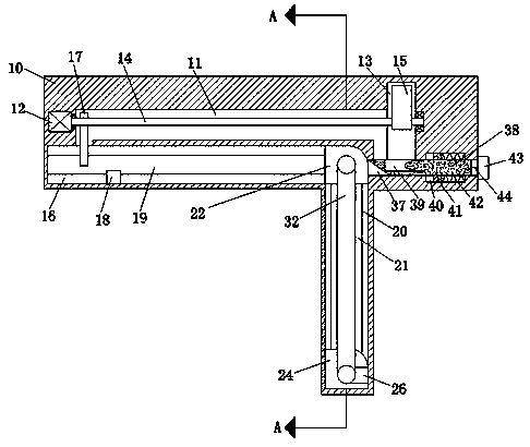
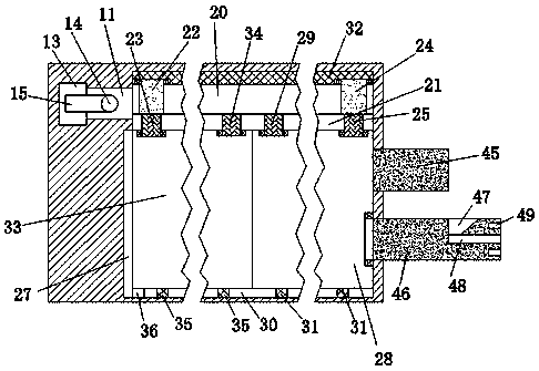
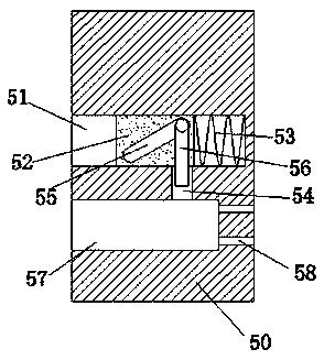

Image

  • Sliding door device
  • Sliding door device
  • Sliding door device

Examples


Embodiment Construction

[0015] Such as Figure 1-Figure 3 As shown, a sliding door device of the present invention includes a device main body 10, a sliding device arranged in the device main body 10, and a locking device arranged in the device main body 10, and the sliding device includes In the first cavity 11 in the device body 10, a first motor 12 is fixedly arranged in the inner wall of the left side of the first cavity 11, and an opening is arranged in the inner wall of the right side of the first cavity 11 to communicate with each other. In the first rotating cavity 13, the right end of the first motor 12 is dynamically connected with a first screw 14 that extends through the first cavity 11 and extends into the first rotating cavity 13, so The first screw rod 14 is fixedly connected with a cam 15 that can rotate in the first rotating cavity 13, and a first sliding cavity 16 is connected in the inner wall of the front side of the first cavity 11. A screw 14 is threadedly connected with a first...


PUM


Abstract

The invention discloses a sliding door device. The sliding device comprises a device body, a sliding device arranged in the device body, and a lock catch device arranged in the device body; and the sliding device comprises a first cavity formed in the device body, a first motor is fixedly arranged in the inner wall of the left side of the first cavity, and a first rotating cavity with a forward opening is formed in the inner wall of the right side of the first cavity in a communicating mode. At present, a push-pull sliding door in a market is mainly a straight-rail-type push-pull sliding door,a door body of the straight-rail-type push-pull sliding door is heavy, certain spaces need to be occupied at the left end and the right ends of the door body for mounting sliding rails, after being closed, the straight-rail-type push-pull sliding door needs to the locked manually by a user, and operation is trouble. According to the sliding door device designed by the invention, a door body is light, the more space can be saved, the hidden property is achieved, and meanwhile, the automatic locking function is achieved.

Description

Technical field [0001] The invention relates to the technical field of smart homes, in particular to a sliding door device. Background technique [0002] At present, the sliding doors on the market are mainly straight-track sliding doors. The straight-track sliding door has a heavier body and requires a certain amount of space on the left and right ends to install the sliding rail. This type of sliding door generally needs to be closed. It is more troublesome for users to manually lock the door. Therefore, it is necessary to design a sliding door device that is lighter and can save more space, is concealed, and has an automatic locking function. Summary of the invention [0003] The technical problem to be solved by the present invention is to provide a sliding door device, which can solve the above-mentioned problems in the current technology. [0004] The present invention is achieved through the following technical solutions: a sliding door device of the present invention includ...

Claims


Application Information

Patent Timeline
Patent Type & Authority Applications(China)
IPC IPC(8): E05F15/652E05B65/08E05B15/00
CPCE05F15/652E05B15/00E05B65/08
Inventor 屠建松
Owner 屠建松
Learn More