Energy-saving flow meter

A flow meter, energy-saving technology, applied in the field of energy-saving flow meters, can solve the problems of gas waste and unadjustable gas pressure

Pending Publication Date: 2019-12-31
NANJING VTECH ELECTRO MECHANICAL TECH DEV
View PDF0 Cites 0 Cited by
  • Summary
  • Abstract
  • Description
  • Claims
  • Application Information

AI Technical Summary

Problems solved by technology

[0002] At present, when the gas flowmeter in the prior art is in use, the

Method used


Image

  • Energy-saving flow meter
  • Energy-saving flow meter

Examples


Embodiment 1

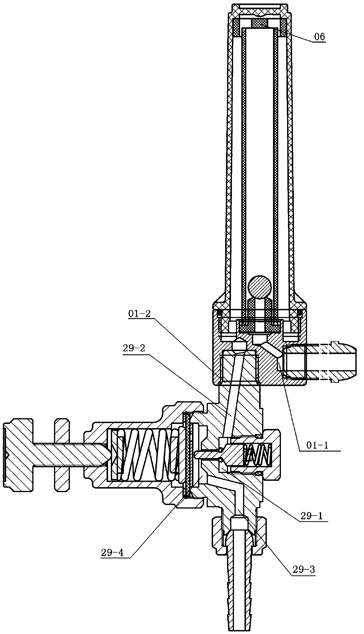
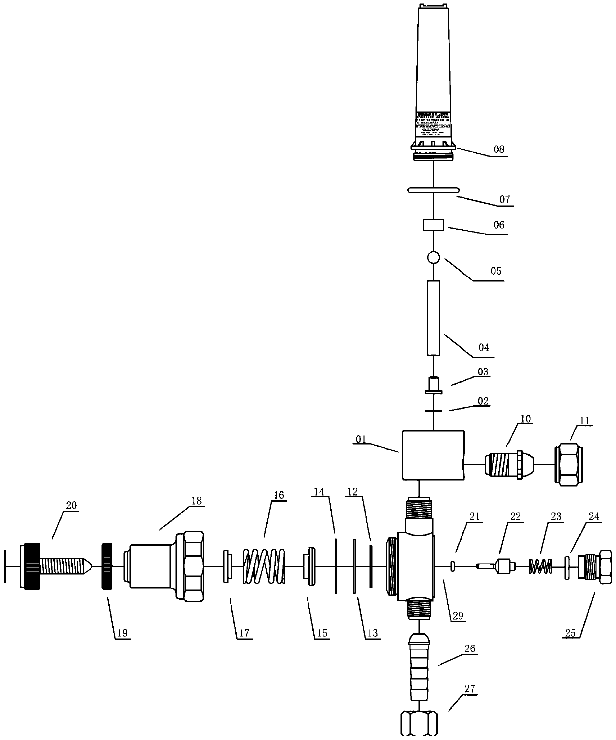
[0023] Such as figure 1 and 2 As shown, an energy-saving flowmeter includes a transparent outer tube 08, a transparent inner tube 04, an inner tube base 03, a flowmeter body 01, a valve body 29, a piston set and a diaphragm assembly.

[0024] Such as figure 1 and 2 As shown, the transparent inner tube 04 and the transparent outer tube 08 are both top-sealed and low-end open, the transparent inner tube 04 is located inside the transparent outer tube 08, a stopper 06 is set on the inner wall of the top of the transparent outer tube 08, and the transparent inner tube 04 and An airway is formed between the transparent outer tubes 08, and the airway communicates with the inner cavity of the transparent inner tube 04; Air channel, place an aluminum bead 05 at the end of the air intake channel of the inner tube base. The diameter of the aluminum bead 05 is smaller than the inner diameter of the transparent inner tube 04 and larger than the inner diameter of the inner tube base air...


PUM


Abstract

The invention discloses an energy-saving flow meter. The energy-saving flow meter comprises a transparent outer pipe, a transparent inner pipe, an inner pipe base, a flow meter body, a valve body, a piston set and a diaphragm assembly. According to the energy-saving flow meter, gas waste in use is reduced to the minimum, and output flow is uniform and stable.

Description

technical field [0001] The present invention relates to an energy-saving flow meter. Background technique [0002] At present, when the gas flowmeter in the prior art is used, the gas waste is large and the pressure of the gas output cannot be adjusted. Contents of the invention [0003] The present invention proposes an energy-saving flowmeter, and the technical solution adopted by the present invention is: [0004] An energy-saving flowmeter comprising a transparent outer tube, [0005] The transparent inner tube is located inside the transparent outer tube, an airway is formed between the transparent inner tube and the transparent outer tube, and the airway communicates with the lumen of the transparent inner tube; [0006] The base of the inner tube, the lower end of the transparent inner tube is inserted into the base of the inner tube, the base of the inner tube is provided with an air inlet channel along the axial direction, and an aluminum bead is movably placed ...

Claims


Application Information

Patent Timeline
IPC IPC(8): G01F1/38G01F15/00F16K1/00F16K1/46
CPCF16K1/00F16K1/46G01F1/38G01F15/005
Inventor 林建州曾素珍
Owner NANJING VTECH ELECTRO MECHANICAL TECH DEV
Why Eureka
Try Eureka