Unlock instant, AI-driven research and patent intelligence for your innovation.

optical lens

An optical lens and lens technology, which is applied in the field of optical lenses to achieve the effect of high relative illumination and small front-end aperture

Active Publication Date: 2022-01-21
NINGBO SUNNY AUTOMOTIVE OPTECH
View PDF0 Cites 0 Cited by
  • Summary
  • Abstract
  • Description
  • Claims
  • Application Information

AI Technical Summary

Problems solved by technology

However, for applications where the installation position of automotive lenses is limited, how to achieve miniaturization on the basis of ensuring high pixels and large chips has become a key issue

Method used


Image

  • optical lens
  • optical lens
  • optical lens

Examples


Embodiment 1

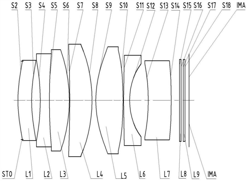
[0080] Refer to the following figure 1 An optical lens according to Embodiment 1 of the present application is described. figure 1 A schematic structural diagram of the optical lens according to Embodiment 1 of the present application is shown.

[0081] Such as figure 1 As shown, the optical lens sequentially includes a first lens L1, a second lens L2, a third lens L3, a fourth lens L4, a fifth lens L5, a sixth lens L6 and a seventh lens along the optical axis from the object side to the imaging side. Lens L7.

[0082] The first lens L1 is a meniscus lens with positive refractive power, the object side S2 is convex, and the image side S3 is concave.

[0083] The second lens L2 is a biconcave lens with negative refractive power, and its object side S4 and image side S5 are both concave. The third lens L3 is a biconvex lens with positive refractive power, and its object side S5 and image side S6 are both convex. Wherein, the second lens L2 and the third lens L3 are glued to...

Embodiment 2

[0105] Refer to the following figure 2 An optical lens according to Embodiment 2 of the present application is described. In this embodiment and the following embodiments, for the sake of brevity, descriptions similar to those in Embodiment 1 will be omitted. figure 2 A schematic structural view of the optical lens according to Embodiment 2 of the present application is shown.

[0106] Such as figure 2 As shown, the optical lens sequentially includes a first lens L1, a second lens L2, a third lens L3, a fourth lens L4, a fifth lens L5, a sixth lens L6 and a seventh lens along the optical axis from the object side to the imaging side. Lens L7.

[0107] The first lens L1 is a meniscus lens with positive refractive power, the object side S2 is convex, and the image side S3 is concave.

[0108] The second lens L2 is a biconcave lens with negative refractive power, and its object side S4 and image side S5 are both concave. The third lens L3 is a biconvex lens with positive ...

Embodiment 3

[0126] Refer to the following image 3 An optical lens according to Embodiment 3 of the present application is described. In this embodiment and the following embodiments, for the sake of brevity, descriptions similar to those in Embodiment 1 will be omitted. image 3 A schematic structural diagram of an optical lens according to Embodiment 3 of the present application is shown.

[0127] Such as image 3 As shown, the optical lens sequentially includes a first lens L1, a second lens L2, a third lens L3, a fourth lens L4, a fifth lens L5, a sixth lens L6 and a seventh lens along the optical axis from the object side to the imaging side. Lens L7.

[0128] The first lens L1 is a meniscus lens with positive refractive power, the object side S2 is convex, and the image side S3 is concave.

[0129] The second lens L2 is a biconcave lens with negative refractive power, and its object side S4 and image side S5 are both concave. The third lens L3 is a biconvex lens with positive r...


PUM


Abstract

The present application discloses an optical lens, and the optical lens may include: a first lens, a second lens, a third lens, a fourth lens, a fifth lens, a sixth lens and Seventh lens. The first lens can have positive refractive power, and its object side is convex, and the image side is concave; the second lens can have negative refractive power, and its object side and image side are concave; the third lens can have positive refractive power, and Both the object side and the image side are convex; the fourth lens can have positive power, the object side is concave, and the image side is convex; the fifth lens can have positive power, and the object side and the image side are convex; the sixth The lens may have negative optical power with a convex object side and concave image side; and the seventh lens may have negative optical power with a concave object side. According to the optical lens of the present application, at least one beneficial effect of miniaturization, high resolution, small aperture at the front end, high relative illuminance, matching large-size chips, etc. can be realized.

Description

technical field [0001] The present application relates to an optical lens, and more particularly, the present application relates to an optical lens including seven lenses. Background technique [0002] At present, lenses are widely used in vehicle-assisted driving systems, and even for automatic driving. As the application environment changes, the quality requirements of the lens are also increasing. The pixel requirements of the optical lens are getting higher and higher, so that the size of the chip increases accordingly, and the size of the entire lens increases accordingly. Especially for automotive optical lenses, high pixels and large chips must become the main development direction. However, for applications where the installation position of automotive lenses is limited, how to achieve miniaturization on the basis of ensuring high pixels and large chips has become a key issue. Contents of the invention [0003] The present application provides an optical lens t...

Claims


Application Information

Patent Timeline
Patent Type & Authority Patents(China)
IPC IPC(8): G02B13/00G02B13/18
CPCG02B13/0045G02B13/18
Inventor 李慧敏王东方姚波
Owner NINGBO SUNNY AUTOMOTIVE OPTECH