Method for pattern generation with improved image quality

Inactive Publication Date: 2002-08-06
MICRONIC LASER SYST AB
View PDF6 Cites 106 Cited by
  • Summary
  • Abstract
  • Description
  • Claims
  • Application Information

AI Technical Summary

Problems solved by technology

Specifically there is a problem with the prior art pattern generation to provide adequate image resolution and fidelity.
By contrast, a deflection system works by deflecting the light to the side and is difficult to make symmetrical around the optical axis at intermediate deflection angles, creating a risk of feature instability when focus is changed.
The tilts of the various parts of the mirrors are unimport

Method used


Image

  • Method for pattern generation with improved image quality
  • Method for pattern generation with improved image quality
  • Method for pattern generation with improved image quality

Examples


third embodiment

A Third Embodiment

A third preferred embodiment is identical to the second embodiment, except that the matrix of pixels is rotated 45 degrees and the pixel grid is 84 .mu.m, giving a projected pixel spacing along x and y of 0.06 .mu.m. The laser is an ArF excimer laser, and the lens has a reduction of 240. Because of the rotated matrix, the density of pixels in the matrix is less, and the data volume is half of the previous embodiment. Nonetheless, the address resolution is the same.

Laser Flash-to-flash Variations

The excimer laser has two unwanted properties, flash-to-flash energy variations of 5% and flash-to-flash time jitter of 100 ns. In the preferred embodiments, both are compensated for in the same way. A first exposure is made of the entire pattern with 90% power. The actual flash energy and time position for each flash are recorded. A second exposure is made with nominally 10% exposure, with the analog modulation used to make the second exposure 5-15%, depending on the actual...


PUM

PropertyMeasurementUnit
Areaaaaaaaaaaa
Wavelengthaaaaaaaaaa
Exposure limitaaaaaaaaaa

Abstract

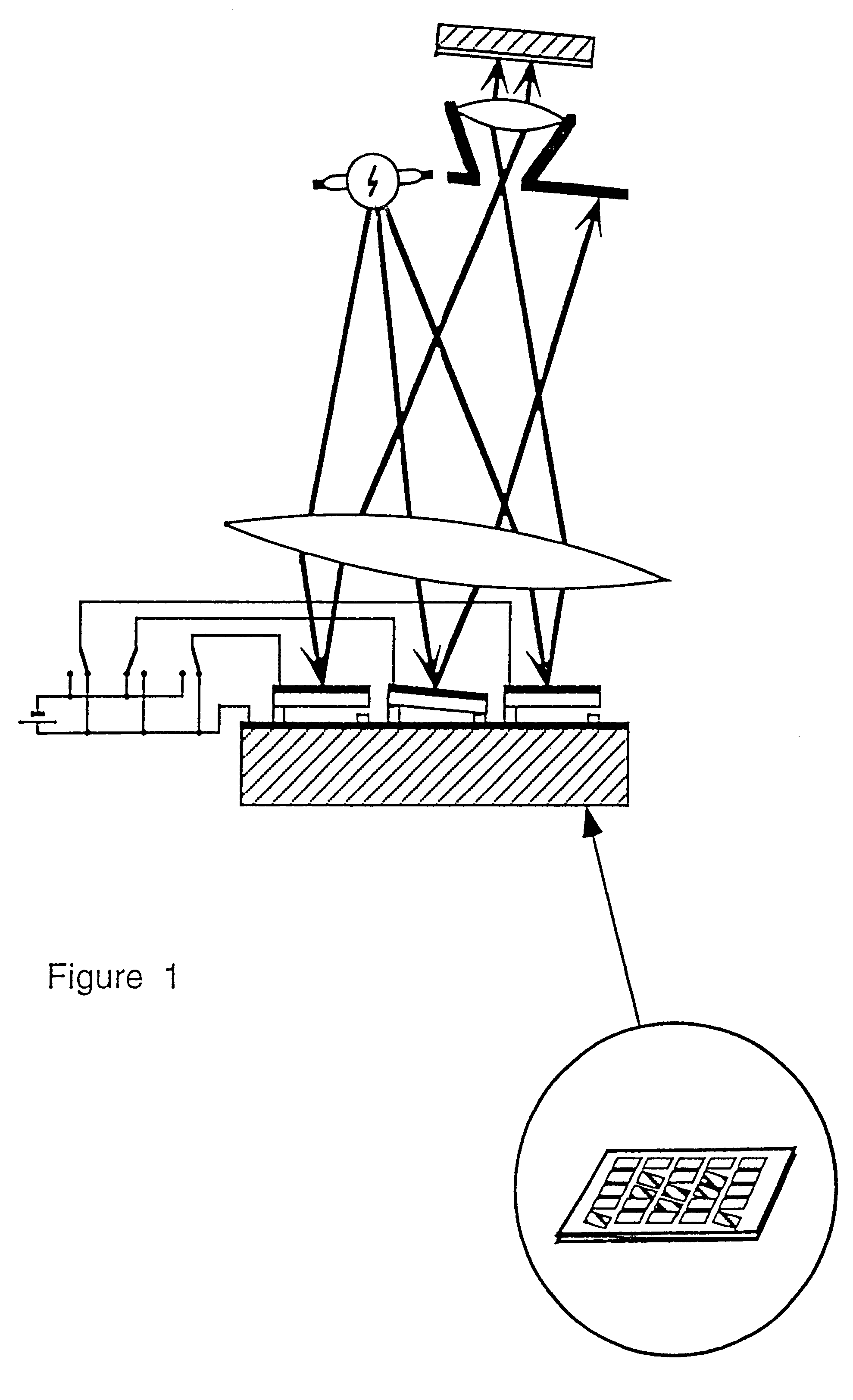
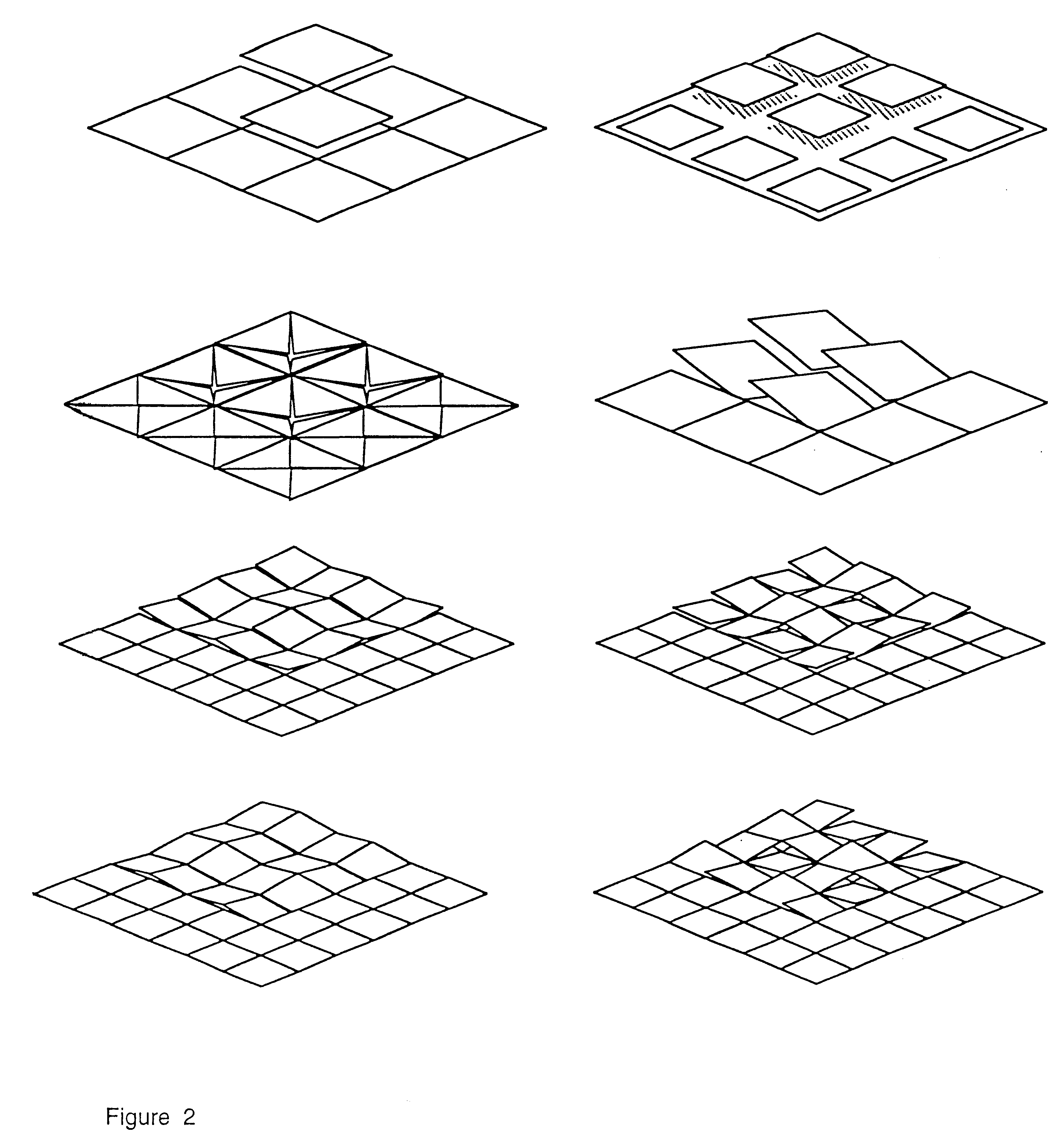
The present invention relates to a method for creating a microlithographic pattern on a workpiece, for increased resolution and image fidelity. The method comprises the steps of: providing a source for emitting electromagnetic radiation, illuminating by said radiation a spatial light modulator (SLM) having several pixels, projecting an image of the modulator on the workpiece, further coordinating the movement of the workpiece, the feeding of the signals to the modulator and the intensity of the radiation, so that said pattern is stitched together from the partial images created by the sequence of partial patterns, where an area of the pattern is exposed at least twice with a change in at least one, and preferably at least two, of the following parameters between the exposures: data driven to the SLM, focus, angular distribution of the illumination at the SLM, pupil filtering, polarisation.

Description

1. Field of the InventionThe present invention relates to printing of patterns with extremely high precision on photosensitive surfaces, such as photomasks for semiconductor devices and displays. It also relates to direct writing of semiconductor device patterns, display panels, integrated optical devices and electronic interconnect structures. Furthermore, it can have applications to other types of precision printing such as security printing. The term printing should be understood in a broad sense, meaning exposure of photoresist and photographic emulsion, but also the action of light on other light sensitive media such as dry-process paper, by ablation or chemical processes activated by light or heat. Light is not limited to mean visible light, but a wide range of wavelengths from infrared (IR) to extreme UV. Of special importance is the ultraviolet range from 370 nm (UV) through deep ultraviolet (DUV), vacuum ultraviolet (WV) and extreme ultraviolet (EUV) down to a few manometer...

Claims


Application Information

Patent Timeline
IPC IPC(8): B23Q17/24G02B26/00G02B26/08G03F7/20H04N1/195B23K26/06G02B26/06G03F1/00G03F1/08G03F7/207H01L21/027H04N5/74
CPCB23K26/032B23K26/0639B23K26/0648G02B26/0833G02B26/0841G02B27/0043G02B27/4205G03F7/2022G03F7/2057G03F7/70041G03F7/70283G03F7/70291G03F7/704G03F7/70475G03F7/70725G09G3/346H04N1/195H04N5/7458B41J2/465G09G3/2007H04N2201/0414B23K26/064G03F7/20
Inventor SANDSTROM, TORBJORN
Owner MICRONIC LASER SYST AB
Why Eureka
Try Eureka