
Cable laying traction device in tunnel

A traction device and cable laying technology, used in cable laying equipment, transportation and packaging, transportation of filamentous materials, etc., can solve the problems of reduced work efficiency, easy slippage, weakened frictional traction, etc., to ensure traction speed, guarantee Work efficiency and the effect of preventing slippage

Pending Publication Date: 2019-12-31
CHINA RAILWAY 12TH BUREAU GRP +1
View PDF0 Cites 3 Cited by
  • Summary
  • Abstract
  • Description
  • Claims
  • Application Information

AI Technical Summary

Problems solved by technology

[0003] Due to the very humid environment in the tunnel, it is very easy to cause the surface of the cable to become wet, which in turn weakens the frictional traction force of the friction wheel in the cable laying traction device to the cable, resulting in a decrease in the cable laying traction speed and work efficiency. Secondly, the frictional traction force is weakened too small, prone to slipping

Method used


Image

  • Cable laying traction device in tunnel
  • Cable laying traction device in tunnel
  • Cable laying traction device in tunnel

Examples


Embodiment Construction

[0023] In order to make the purpose, technical solutions and advantages of the embodiments of the present invention clearer, the technical solutions in the embodiments of the present invention will be clearly and completely described below. Obviously, the described embodiments are part of the embodiments of the present invention, rather than All the embodiments; based on the embodiments of the present invention, all other embodiments obtained by persons of ordinary skill in the art without creative work all belong to the protection scope of the present invention.

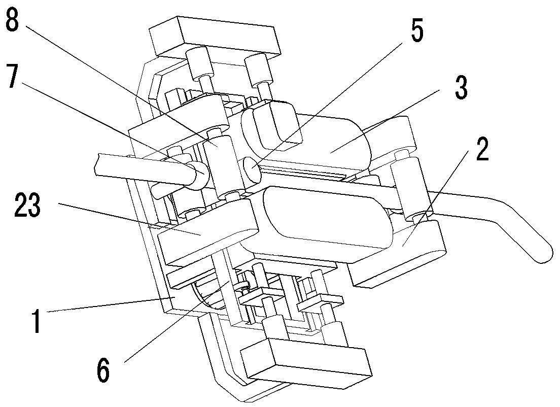
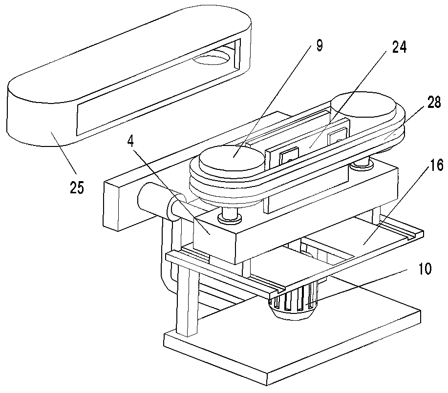
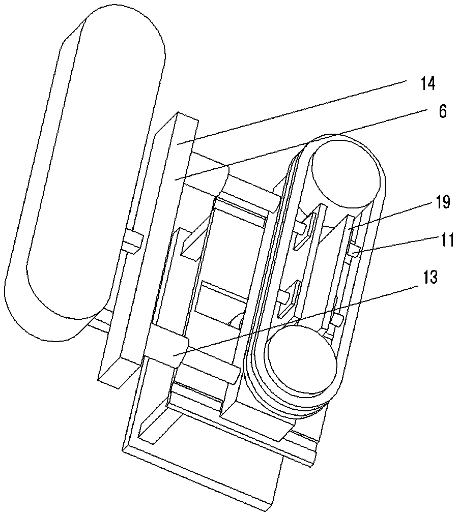
[0024] Such as Figure 1-6 As shown, the embodiment of the present invention provides a traction device for cable laying in a tunnel, including a device base 1, a guide mechanism 2, a traction mechanism 3 and a speed measuring assembly 5, wherein the two guide mechanisms 2 are respectively fixed and installed on the device base At the left and right ends of 1, the speed measuring assembly 5 is fixedly arranged on th...


PUM


Abstract

The invention belongs to the tunnel construction field and discloses a cable laying traction device in a tunnel. The device comprises a device pedestal, guide mechanisms, a traction mechanism and a speed measurement component. The two guide mechanisms are fixedly installed at left and right ends of a traction device main body. The traction mechanism is arranged between the two guide mechanisms andis movably installed on the device pedestal through a friction force adjusting mechanism, and a cable enters from one guide mechanism, penetrates through the speed measurement component and the traction mechanism and then leaves from the other guide mechanism. The friction force adjusting mechanism comprises an upper pedestal, an electromagnetic telescopic column and a sliding block. The upper pedestal is fixedly arranged above the device pedestal, two sliding grooves are arranged on an upper surface, a bottom of the traction mechanism is fixedly connected with tops of sliding blocks arrangedin the sliding grooves, one end of the electromagnetic telescopic column is fixedly connected with the device pedestal through a connecting mechanism, and the other end of the electromagnetic telescopic column is fixedly connected with a side surface of a speed reducer. In the invention, a traction speed of a cable can be ensured, and cable laying efficiency is improved.

Description

technical field [0001] The invention relates to the technical field of tunnel cable construction, in particular to a traction device for cable laying in a tunnel. Background technique [0002] Cable laying refers to the process of laying and installing cables along the surveyed route to form a cable route. According to the application occasion, it can be divided into several laying methods such as overhead, underground (pipeline and direct burial), underwater, wall and tunnel. Reasonable selection of cable laying method is very important to ensure the transmission quality, reliability and construction maintenance of the line. [0003] Due to the very humid environment in the tunnel, it is very easy to cause the surface of the cable to become wet, which in turn weakens the frictional traction force of the friction wheel in the cable laying traction device to the cable, resulting in a decrease in the cable laying traction speed and work efficiency. Secondly, the frictional tr...

Claims


Application Information

Patent Timeline
IPC IPC(8): H02G1/06B65H51/14
CPCB65H51/14H02G1/06
Inventor 张异凡李永强辛东红梁卫兵张杰
Owner CHINA RAILWAY 12TH BUREAU GRP
Learn More