Method for quickly determining installation angle of aircraft wing

A technology for installing angles and wings, which is applied to aircraft assembly, aircraft parts, ground devices, etc., can solve the problems of long calculation cycle, aerodynamic calculation or wind tunnel test workload, long cycle, etc., so as to save workload and simplify The effect of the wing installation angle determination procedure

Active Publication Date: 2020-01-03
HARBIN
View PDF7 Cites 9 Cited by
  • Summary
  • Abstract
  • Description
  • Claims
  • Application Information

AI Technical Summary

Problems solved by technology

[0004]The advantage of the first method is that it is simple, and the disadvantage is that it does not consider the specific influence of the aircraft design parameters, and is determined by the statistical average
The advantage of the second method is that it takes into account the influence of aircraft design parameters on the installation angle of the wing, but the disadvantage is that the aerodynamic calculation or wind tunnel test has a large workload and a long cycle
This invention is to calculate the aerodynamic characteristics of the entire amphibious hovercraft. Since the trim lift and resistance of the horizontal tail will affect the lift-drag ratio of the entire hovercraft, the installation angle of the wings should be determined iteratively. The overall program is complicated, the calculation amount is large, and the calculation cycle is long.

Method used


Image

  • Method for quickly determining installation angle of aircraft wing
  • Method for quickly determining installation angle of aircraft wing
  • Method for quickly determining installation angle of aircraft wing

Examples


Embodiment Construction

[0032] In order to make the purpose, technical solution and advantages of the present application clearer, the present application will be further described in detail below in conjunction with the accompanying drawings and specific embodiments. For simplicity, some technical features known to those skilled in the art are omitted from the following description.

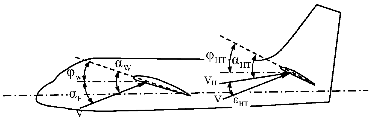
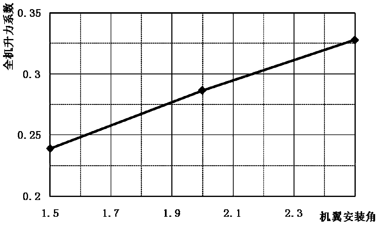
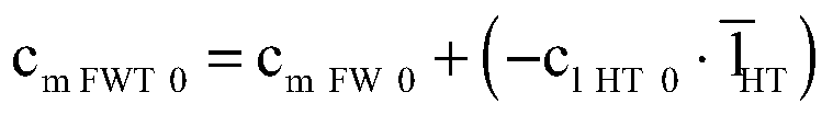
[0033] In a certain implementation case, the present invention decomposes the overall aerodynamic characteristics of a civil aircraft with conventional layout into the aerodynamic characteristics of the wing / body assembly and the flat tail aerodynamic characteristics, based on the cruise design point conditions, that is, the cruise lift coefficient is given and the pitch angle of the fuselage is zero 1. The pitching moment of the whole aircraft is zero. Through appropriate assumptions, the pitching moment and lift characteristic data of the wing / body assembly at zero angle of attack are reasonably used to quickly determ...


PUM


Abstract

The invention belongs to the pneumatic layout technology of a conventional pneumatic layout aircraft, and relates to a method for determining an installation angle of a conventional pneumatic layout aircraft wing. The method for quickly determining the installation angle of the aircraft wing comprises the following steps that a preliminary wing installation angle is firstly given, and only a knownpitching moment coefficient of a zero angle of attack wing and fuselage combination body is needed, a horizontal tail lift force coefficient is calculated through a whole-aircraft pitching moment balance condition, and in the case that the horizontal tail lift force coefficient and a wing and fuselage combination body lift force coefficient are known, a whole-aircraft lift coefficient is obtained; a series of wing installation angles are given, and the relationship between the whole-aircraft lift coefficient and the wing installation angle is obtained under conditions that the angle of attackof the fuselage is zero and the whole-aircraft pitch moment coefficient is zero; and based on the cruise design point condition, the final wing installation angle is determined by interpolation according to the cruise whole-aircraft lift coefficient. The method has the advantages that the calculation amount is small, the size of the installation angle of the traditional pneumatic layout wing canbe directly and rapidly determined, the aerodynamic property calculation or wind tunnel test workload is effectively saved, and the method has relatively large practical application value.

Description

technical field [0001] The invention belongs to the aerodynamic layout technology of conventional aerodynamic layout aircraft, and relates to a method for determining the wing installation angle of conventional aerodynamic layout aircraft. Background technique [0002] When designing the aerodynamic layout of an aircraft, it is necessary to determine the installation angle of the wing, which is the angle between the chord line at the root of the wing and the horizontal line of the aircraft fuselage. Wing installation angle is a basic parameter of aircraft aerodynamic layout design, which has an important influence on aircraft aerodynamic layout. [0003] Usually, there are two ways to determine the wing installation angle: (1) directly determine the wing installation angle by counting the wing installation angles of the same type of aircraft; Hole test to determine the wing installation angle. [0004] The advantage of the first method is that it is simple, and the disadva...

Claims


Application Information

Patent Timeline
Patent Type & Authority Applications(China)
IPC IPC(8): B64F5/00B64F5/10
CPCB64F5/00B64F5/10Y02T90/00
Inventor 张德平董振林刘佳惠
Owner HARBIN
Why Eureka
Try Eureka