
Indoor ceiling and construction method thereof

A ceiling and suspended ceiling technology, applied in the direction of ceilings, building components, buildings, etc., can solve problems such as poor sealing, and achieve the effect of reducing poor sealing and improving sealing.

Inactive Publication Date: 2020-01-03
NANTONG BUILDING DECORATION DECORATION
View PDF5 Cites 0 Cited by
  • Summary
  • Abstract
  • Description
  • Claims
  • Application Information

AI Technical Summary

Problems solved by technology

[0004] The above-mentioned existing technical solutions have the following defects: but the above-mentioned installation method makes the sealing of the connection between adjacent ceilings poor, so it needs to be improved

Method used


Image

  • Indoor ceiling and construction method thereof
  • Indoor ceiling and construction method thereof
  • Indoor ceiling and construction method thereof

Examples


Embodiment 1

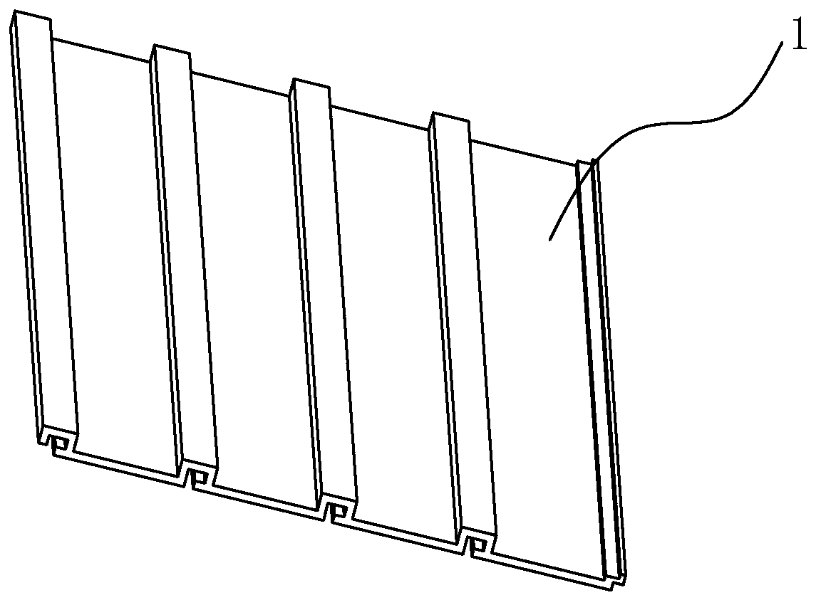
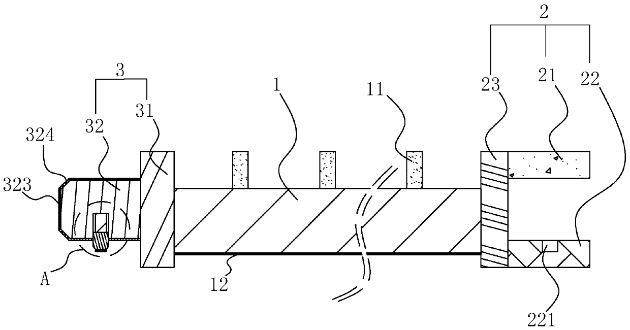
[0042] A kind of indoor ceiling suspended ceiling, refer to figure 2 , which includes a ceiling floor 1, the two sides of the ceiling floor 1 are respectively integrally formed with a first clip 2 and a second clip 3, the first clip 2 and the second clip 3 on the adjacent ceiling floor 1 can be locked together Connection; the first clip 2 includes a first horizontal plate 21, a second horizontal plate 22 and a first vertical plate 23 between the first horizontal plate 21 and the second horizontal plate 22, the first horizontal plate 21, the second horizontal plate A clamping area is formed between the plate 22 and the first vertical plate 23 .

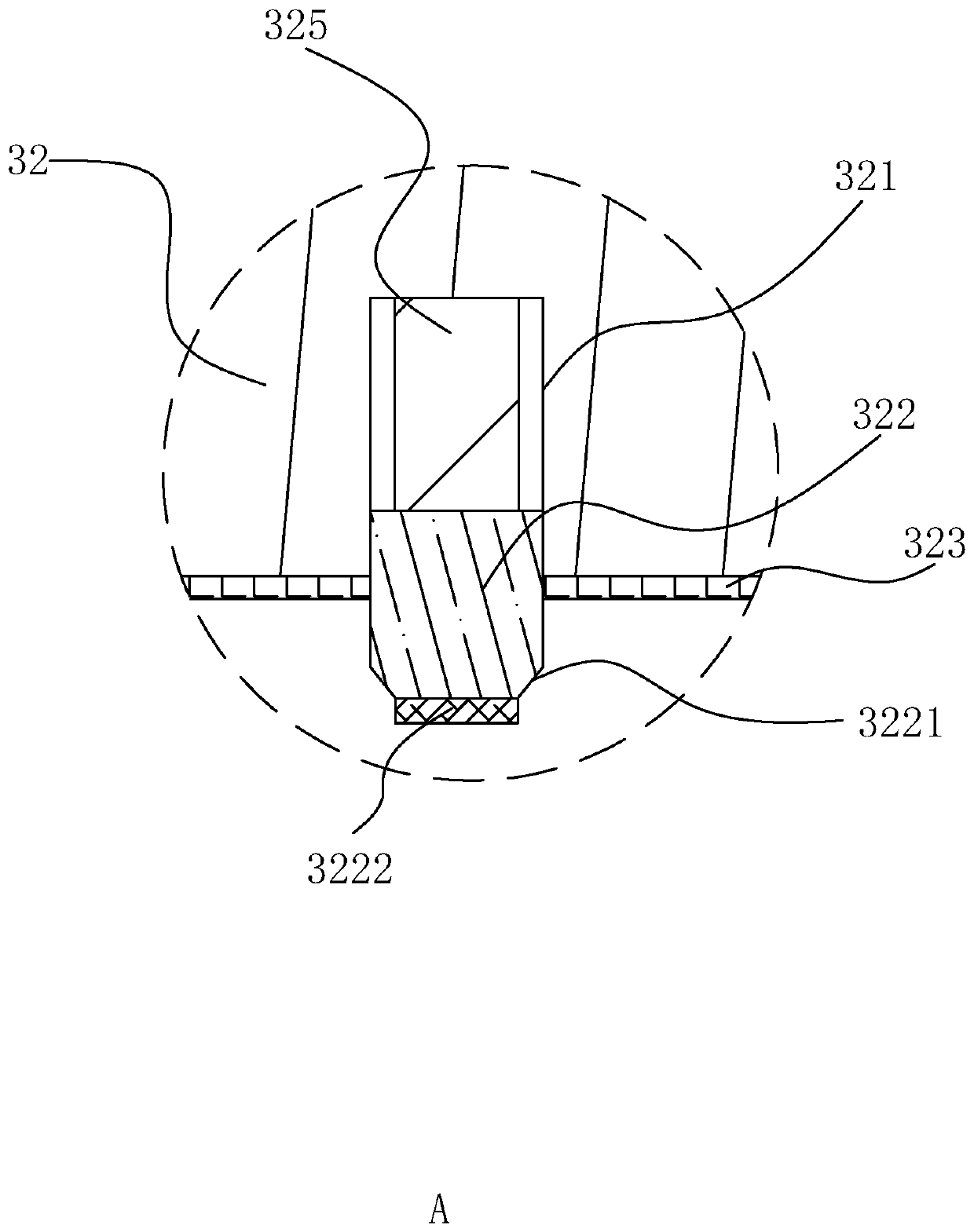
[0043] refer to figure 2 , the second clip 3 includes a second vertical plate 31 and a third horizontal plate 32 perpendicular to the second vertical plate 31, the third horizontal plate 32 can be adapted to be inserted in the clamping area, the third horizontal plate 32 A second guide surface 324 is provided at the end away from t...

Embodiment 2

[0050] A construction method for indoor ceiling suspension, comprising the steps of:

[0051] S1: Determine the location, the operator shall measure according to the field, and determine the location and number of holes to be drilled according to the installation location and overall area of ​​the suspended ceiling;

[0052] S2: Drilling, the operator punches holes on the wall according to the determined position, puts the three-piece sets of expansion screws into the holes one by one, and knocks them with a hammer;

[0053] S3: Keel installation, the operator connects the main keel and the auxiliary keel with hanging parts, and hangs them directly on the expansion screws;

[0054] S4: To close the edge strip, place the wooden block on the place where the hole is punched, and fix it with glass glue;

[0055] S5: Installing, engaging the first clip 2 of the ceiling body with the second clip 3 on the adjacent ceiling floor 1, at this time, the clip 322 is inserted into the clip...


PUM


Abstract

The invention discloses an indoor ceiling and a construction method thereof, relates to the technical field of house construction, and aims to solve the technical problem of poor sealability in connection between adjacent ceilings. The invention provides the technical scheme point that a first clamping piece and a second clamping piece are arranged on two sides of a ceiling bottom plate; the firstclamping piece can be mutually clamped with a second clamping piece on an adjacent ceiling bottom plate; each first clamping piece comprises a first horizontal plate, a second horizontal plate and afirst vertical plate located between the first horizontal plate and the second horizontal plate; each second clamping piece comprises a second vertical plate and a third horizontal plate perpendicularto the second vertical plate; a storage groove is formed in each third horizontal plate; a clamping block is inserted into the corresponding storage groove; a clamping groove for inserting the corresponding clamping block is formed in the corresponding second horizontal plate; the depth of each clamping groove is smaller than the length of each clamping block; and a waterproof glue layer is arranged on the outer side wall of each third horizontal plate. An effect on improving the sealability in connection between the adjacent ceilings is achieved.

Description

technical field [0001] The invention relates to the technical field of house construction, more specifically, it relates to a suspended ceiling for an indoor ceiling and a construction method thereof. Background technique [0002] At present, the indoor ceiling is an important subdivision of architectural decoration engineering. The ceiling has the functions of heat preservation, heat insulation, sound insulation, making up for the defects of the house itself, increasing the layering of the space, convenient for supplementing light sources, easy to clean, and sound absorption. , It is also the hidden layer of electrical, ventilation and air conditioning, communication and fire protection, alarm pipeline equipment and other projects. [0003] Ceiling ceiling of prior art, with reference to figure 1 , including the ceiling base plate 1, and the suspended ceiling base plate 1 is independently installed on the ceiling keel. [0004] The above-mentioned existing technical solut...

Claims


Application Information

Patent Timeline
IPC IPC(8): E04B9/06E04B9/22E04B9/00
CPCE04B9/001E04B9/06E04B9/22
Inventor 陈健马建权陈斌
Owner NANTONG BUILDING DECORATION DECORATION
Features
  • Generate Ideas
  • Intellectual Property
  • Life Sciences
  • Materials
  • Tech Scout
  • Unparalleled Data Quality
  • Higher Quality Content
  • 60% Fewer Hallucinations
Learn More