
Light distribution element, light source module and lamp

A light distribution element and light source technology, applied in the field of lighting, can solve the problems of dim ceiling area, low light directivity, high cost of ceiling lamps or light strips, etc., and achieve the effect of improving lighting comfort

Pending Publication Date: 2020-01-03
SUZHOU OPPLE LIGHTING
View PDF0 Cites 3 Cited by
  • Summary
  • Abstract
  • Description
  • Claims
  • Application Information

AI Technical Summary

Problems solved by technology

In order to improve the comfort of lighting, ceiling lamps or light strips are generally installed on the ceiling. The light directivity of the ceiling lamps or light strips is low, and a small amount of light will shine on the ceiling area, but the cost of the ceiling lamps or light strips Tall and difficult to install and still have the problem of dim ceiling area

Method used


Image

  • Light distribution element, light source module and lamp
  • Light distribution element, light source module and lamp
  • Light distribution element, light source module and lamp

Examples


Embodiment 1

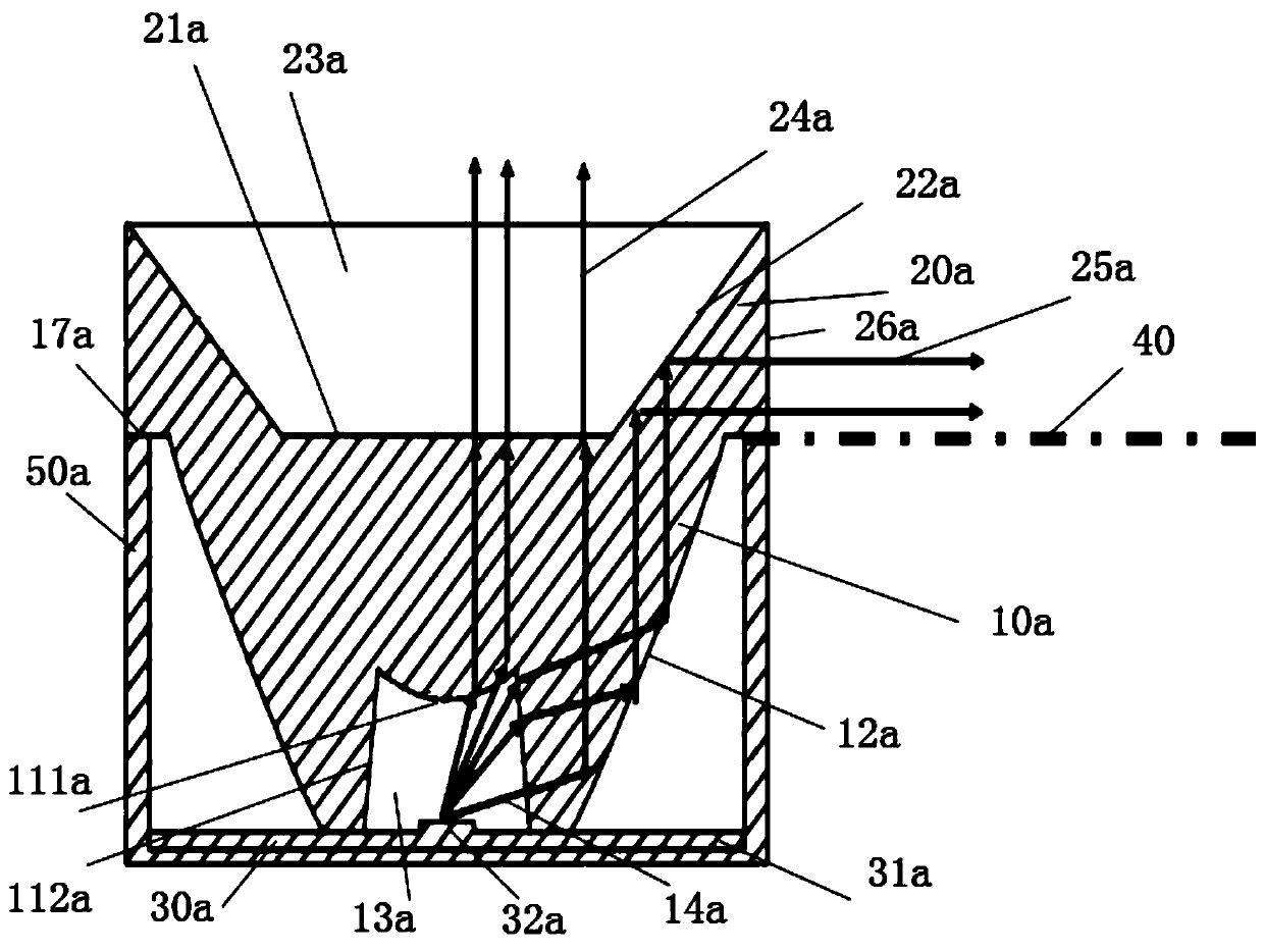
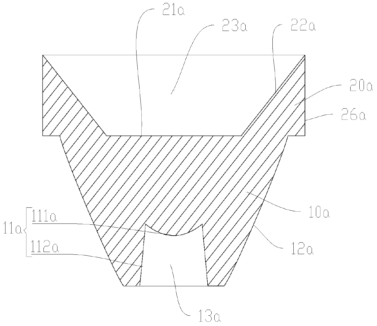
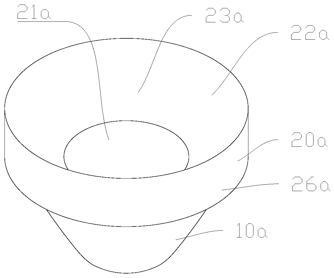
[0041] Such as figure 1 As shown, this embodiment discloses a lamp. The lamp includes a light source module. The light source module includes a light source assembly 30a and a light distribution element. The light source assembly 30a includes a light source substrate 31a and a light source 32a. The light source 32a is mounted on the light source substrate 31a. on. The light distribution element includes a light entrance surface 11a, a first light exit surface 21a, and a second light exit surface 22a. The first light exit surface 21a is configured to receive and emit part of the light entering the light entrance surface 11a; the second light exit surface 22a is a reflective surface. The two light-emitting surfaces 22a are configured to receive and reflect part of the light entering the light-incident surface 11a; the direction of the light emitted by the second light-emitting surface 22a is different from the direction of the light emitted by the first light-emitting surface 21a....

Embodiment 2

[0055] Such as Figure 5 As shown, this embodiment discloses a lamp. The lamp includes a light source module including a light source assembly 30b and a light distribution element. The light source assembly 30b includes a light source substrate 31b and a light source 32b. The light source 32b is mounted on the light source substrate 31b. . The light distribution element includes a light entrance surface 11b, a first light exit surface 21b, and a second light exit surface 22b. The first light exit surface 21b is configured to receive part of the light entering the light entrance surface 11b and emit it; the second light exit surface 22b is a reflective surface. The two light-emitting surfaces 22b are configured to receive and reflect part of the light entering the light-incident surface 11b; the direction of the light emitted by the second light-emitting surface 22b is different from the direction of the light emitted by the first light-emitting surface 21b. The light rays emitt...


PUM


Abstract

The invention relates to a light distribution element, a light source module and a lamp. The light distribution element comprises a light-in surface, a first light-out surface and a second light-out surface, wherein the first light-out surface is configured to receive and emit a part of light entering the light-in surface; the second light-out surface is a reflective surface and is configured to receive and reflect a part of the light entering the light-in surface; and the light emitted by the second light-out surface and the light emitted by the first light-out surface are different in direction and can be used for accent lighting and ceiling region illumination respectively. The light source module comprises a light source and the light distribution element, wherein a light-in surface isconfigured to receive light emitted by the light source. The lamp comprises a housing, the light source and the light distribution element, wherein a light-in surface is configured to receive the light emitted by the light source, the housing is provided with a first light outlet and a second light outlet, the light emitted by the first light-out surface is configured to be emitted from the firstlight outlet, and the light emitted by the second light-out surface is configured to be emitted from the second light outlet.

Description

Technical field [0001] The invention relates to the field of lighting technology, in particular to a light distribution element, a light source module and a lamp. Background technique [0002] Spotlight is a kind of lamps used for accent lighting, widely used in homes, shopping malls, hotels and other places. The spotlight includes a light source and a light-distributing element. The light-distributing element is generally a reflector and / or lens. The light-distributing element enables the light source to have a narrow beam angle, thereby enabling accent lighting and illuminating downward toward the target position. [0003] Since the existing spotlight mainly illuminates the target position downward, the ceiling area will be very dim, which reduces the lighting comfort of the lamp. In order to improve the comfort of lighting, the existing ceiling lights or light strips are generally installed on the ceiling. The light directivity of the ceiling lights or light strips is low, and ...

Claims


Application Information

Patent Timeline
IPC IPC(8): F21S8/02F21V5/04F21V7/00F21V15/01F21V19/00F21Y115/10
CPCF21S8/02F21V5/04F21V7/00F21V15/01F21V19/001F21Y2115/10
Inventor 卜晨曦
Owner SUZHOU OPPLE LIGHTING
Learn More