Applying method for photovoltaic modules integrated in a building

A technology of photovoltaic modules and application methods, which is applied to the support structure of photovoltaic modules, monitoring of photovoltaic modules, photovoltaic systems, etc. Effect

Active Publication Date: 2018-06-08
米兰综合工科大学
View PDF9 Cites 0 Cited by
  • Summary
  • Abstract
  • Description
  • Claims
  • Application Information

AI Technical Summary

Problems solved by technology

This solution does not consider the transparency of the photovoltaic module as a useful property, and the BIPV module does not bend

Method used


Image

  • Applying method for photovoltaic modules integrated in a building
  • Applying method for photovoltaic modules integrated in a building
  • Applying method for photovoltaic modules integrated in a building

Examples


Embodiment Construction

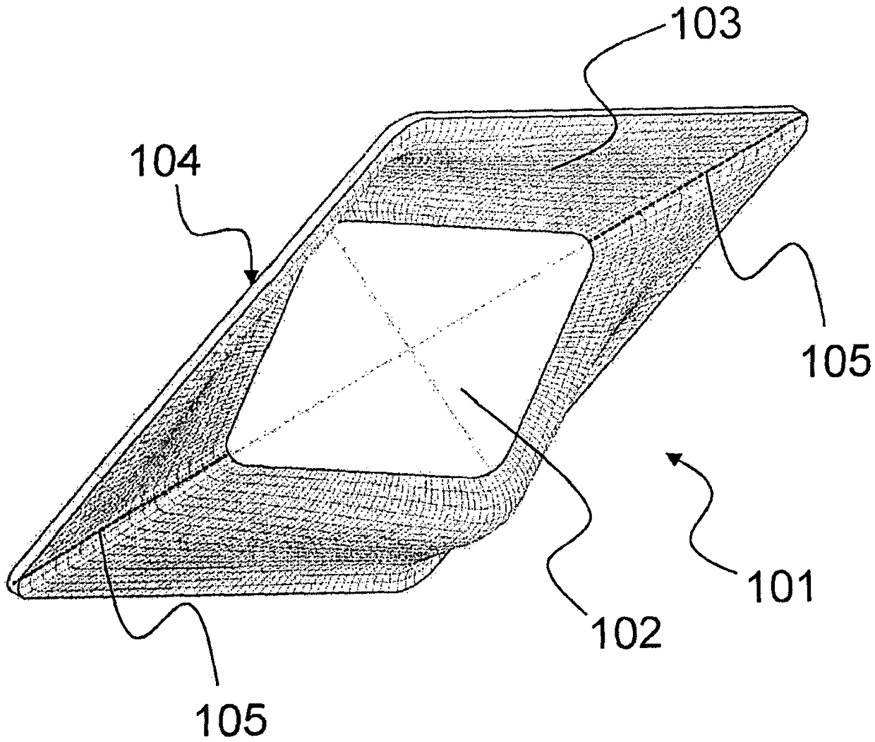
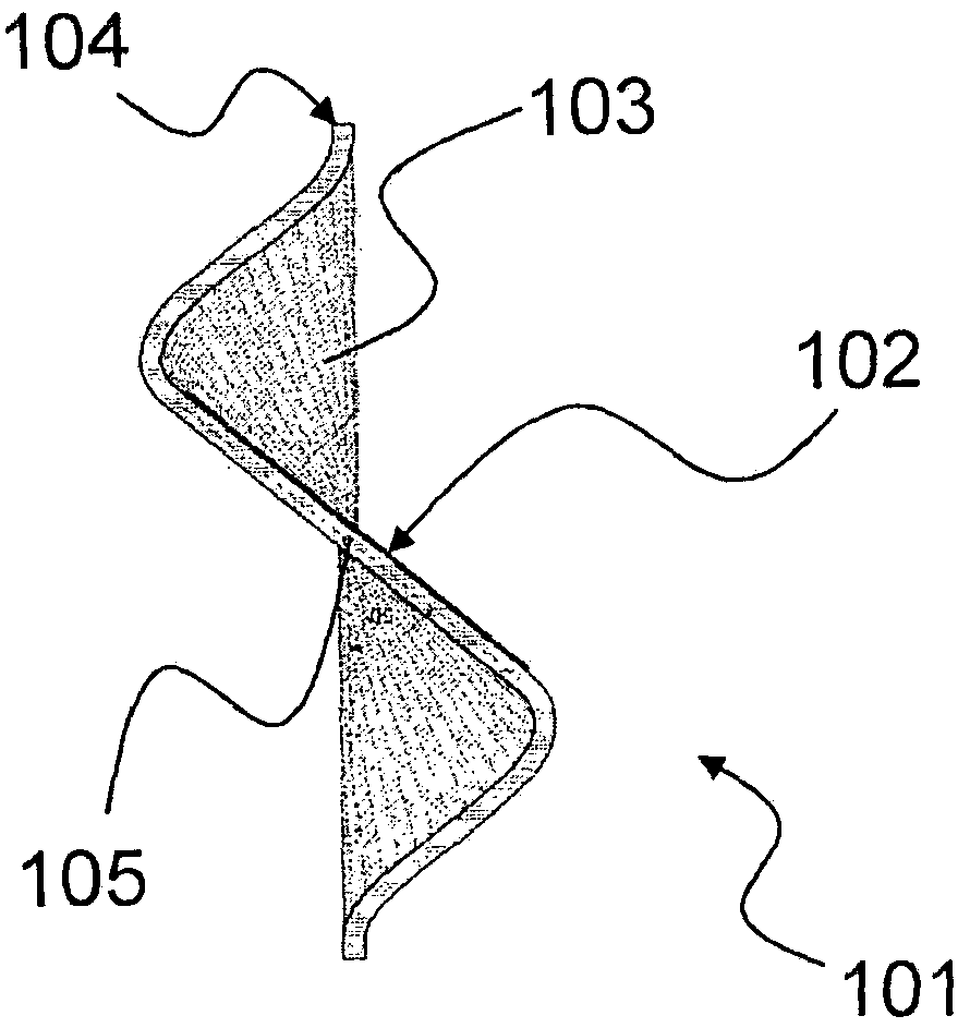
[0051] figure 1 One embodiment of a photovoltaic module 101 according to the invention is shown.

[0052] The photovoltaic module 101 comprises planar photovoltaic elements 102 incorporating photovoltaic cells for converting solar energy into electrical energy.

[0053] The photovoltaic module 101 also includes a suitably bent and shaped rigid support element 103 configured to receive the planar photovoltaic element 102 .

[0054]The rigid support element 103 comprises an outer boundary 104 having a planar perimeter, ie extending in a single through-plane. Said outer boundary 104 allows the application of the entire photovoltaic module 101 on a frame associable to the vertical walls of the building, in particular by laying next to each other a plurality of photovoltaic modules constrained via rigid support elements, as will be described in more detail below of.

[0055] The rigid support element 103 comprises a central support surface with a housing for the photovoltaic ele...


PUM


Abstract

The present invention relates to a method of application of photovoltaic modules integrated into a building (501), each one (101) of said photovoltaic modules comprising a planar photovoltaic element(102) and a rigid support element (103), wherein a plurality (601) of said photovoltaic modules are tiled next to each other and constrained by means of said rigid support element (103) for integration into a vertical wall (602) of said building (501), and wherein said rigid support element (103) is configured for housing said planar photovoltaic element (102) so as to define an angle between thesurface of said planar photovoltaic element (102) and the surface of said vertical wall (602), said method being characterized in that it comprises: defining a plurality of facade parameters (502, 503, 504) for said vertical wall (602) of said building (501), said facade parameters (502, 503, 504) comprising: cardinal orientation (503) of said vertical wall (602), application height (502) available on said vertical wall (602); further defining a plurality of application parameters (511, 512, 513, 514) relating to the distribution of said photovoltaic modules over said wall, said application parameters depending on typological characteristics of said photovoltaic modules (101, 601) applicable along a vertical and/or horizontal coordinate associated with said vertical wall (602); defining apriority function (520) associated with said application parameters (511, 512, 513, 514) and variable along said vertical and/or horizontal coordinate, said priority function providing: a priority preponderance for an illumination parameter (511) in the upper part of the wall; a first priority preponderance for a visibility parameter (512) at the average height of the head of a user (506); a second priority preponderance for a glare control parameter at the average height of the user's head; a priority preponderance for an opacity parameter in the lower part of the wall; a priority maximization anywhere for a photovoltaic area parameter; according to said facade parameters (502, 503, 504), said application parameters (511, 512, 513, 514) and said priority function (520), determining saidtypological characteristics of each one of said photovoltaic modules (101) along said vertical and/or horizontal coordinate, and further calculating values for said angle of each one of said photovoltaic modules (101) along said vertical and/or horizontal coordinate; and applying said photovoltaic modules (601) to said vertical wall (602) according to said determined typological characteristics and said calculated values of said angle.

Description

technical field [0001] The invention relates to a method of application of photovoltaic modules integrated into buildings. [0002] In general, the invention finds application in the field of photovoltaic panels integrated into buildings, ie in the field of BIPV (Building Integrated Photovoltaics). Background technique [0003] It is known to use photovoltaic modules with a flat glass substrate on which crystalline silicon or thin-film photovoltaic elements, usually encapsulated in thin sheets, are applied. [0004] However, while such photovoltaic modules allow vertical positioning on the walls of buildings like BIPV, they provide poor energy efficiency due to optical reflection of light that cannot hit the surface of the photovoltaic element vertically. [0005] Document CN104037254 proposes positioning a plurality of flat photovoltaic modules onto a curved frame. Similarly, document FR2953645 proposes the application of flat photovoltaic modules to curved frames with lo...

Claims


Application Information

Patent Timeline
Patent Type & Authority Applications(China)
IPC IPC(8): H02S50/00H02S20/22
CPCH02S20/26H02S50/00Y02B10/10Y02E10/50
Inventor N·亚基察A·扎纳利
Owner 米兰综合工科大学
Why Eureka
Try Eureka