
Friction electric rotational speed sensing device, shaft assembly and calibration method

A technology of speed sensing and triboelectricity, applied to devices using electric/magnetic methods, measuring devices, speed/acceleration/impact measurement, etc., can solve problems such as high cost, complex structure, and difficult integration of rotating mechanical parts. Achieve the effect of high speed detection accuracy, high stability and consistency, and simple structure

Pending Publication Date: 2020-01-03
BEIJING INST OF NANOENERGY & NANOSYST
View PDF7 Cites 3 Cited by
  • Summary
  • Abstract
  • Description
  • Claims
  • Application Information

AI Technical Summary

Problems solved by technology

[0002] The existing speed sensor can measure the speed of rotating machinery after connecting to an external power supply, and its structure is more complicated, the cost is higher, it is not easy to integrate with rotating machinery parts such as bearings, shafts and gears, and the detection accuracy and stability need to be improved

Method used


Image

  • Friction electric rotational speed sensing device, shaft assembly and calibration method
  • Friction electric rotational speed sensing device, shaft assembly and calibration method
  • Friction electric rotational speed sensing device, shaft assembly and calibration method

Examples


Embodiment Construction

[0034] Embodiments of the present invention will be further described in detail below in conjunction with the accompanying drawings and examples. The detailed description and drawings of the following embodiments are used to illustrate the principle of the present invention, but not to limit the scope of the present invention, that is, the present invention is not limited to the described embodiments.

[0035] In the description of the present invention, it should be noted that, unless otherwise stated, the terms "first" and "second" are only used for descriptive purposes, and cannot be understood as indicating or implying relative importance; The meaning is two or more; the orientation or positional relationship indicated by the terms "inner", "outer", "top", "bottom" etc. is based on the orientation or positional relationship shown in the drawings, and is only for the convenience of describing this The invention and the simplified description do not indicate or imply that th...


PUM


Abstract

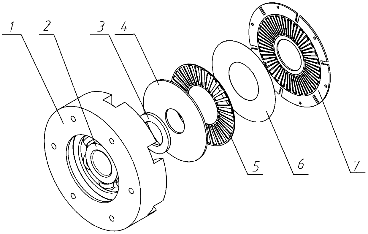
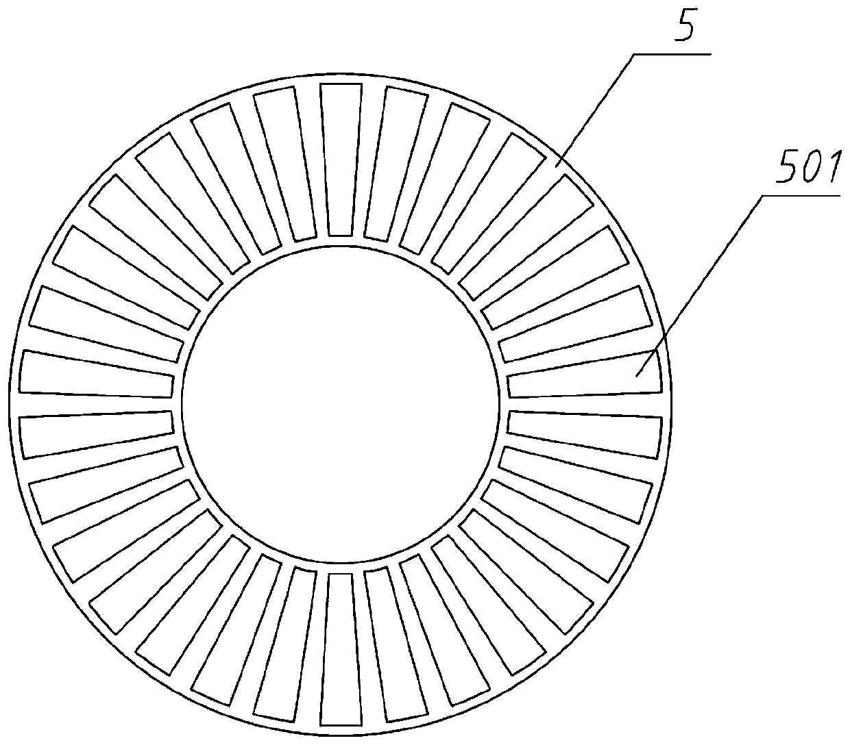
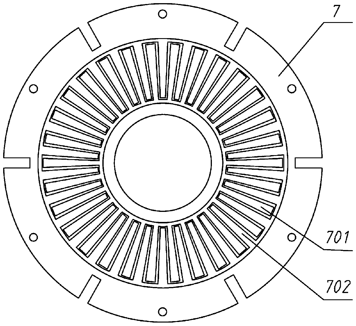
The invention discloses a friction electric rotational speed sensing device, a shaft assembly and a calibration method. The friction electric rotational speed sensing device comprises a rotor structure and a stator structure, wherein the rotor structure comprises a rotor substrate plate and a pair of rotor friction, a rotation piece fixedly sleeves the rotor substrate plate, the stator structure comprises a stator substrate plate and a pair of stator friction, the stator substrate plate is fixedly arranged relative to the rotation piece, the pair of stator friction is in contact with the pairof rotor friction, the pair of rotor friction and the pair of stator friction rotate and friction relative to each other and are in live-line way when the rotation piece rotates, the pair of rotor friction is provided with a grid mouth, the pair of stator friction is arranged at the stator substrate plate by a first electrode and a second electrode, the first electrode and the second electrode areseparated from each other and are alternatively arranged along a circumferential direction of the rotation piece, the first electrode and the second electrode communicate with each other by a wire, and the first electrode and the second electrode can be alternatively overlapped with the grid mouth of the pair of rotor friction in an axial direction of the rotation piece. An external power supplyis not needed, the friction electric rotational speed sensing device is simple in structure and high in detection accuracy and stability and is easy to integrate.

Description

technical field [0001] The invention relates to the technical field of rotational speed sensors, in particular to a triboelectric rotational speed sensing device, a shaft assembly and a calibration method. Background technique [0002] The existing speed sensor can measure the speed of rotating machinery after connecting to an external power supply, and its structure is more complicated, the cost is higher, it is not easy to integrate with rotating machinery parts such as bearings, shafts and gears, and the detection accuracy and stability need to be improved . Contents of the invention [0003] Embodiments of the present invention provide a triboelectric rotational speed sensing device, a shaft assembly and a calibration method, which can be self-driven for sensing, and can be easily integrated with rotating mechanical components. [0004] On the one hand, the embodiment of the present invention proposes a triboelectric speed sensing device, including: a rotor structure,...

Claims


Application Information

Patent Timeline
Patent Type & Authority Applications(China)
IPC IPC(8): G01P3/48G01P21/02
CPCG01P3/48G01P21/02
Inventor 程廷海解志杰其他发明人请求不公开姓名
Owner BEIJING INST OF NANOENERGY & NANOSYST
Learn More