Novel self-driven modular current limiting device

A technology for driving modules and current limiting devices, applied to power devices inside switches, emergency protection circuit devices for limiting overcurrent/overvoltage, circuit devices, etc., to facilitate modular design, meet economy and compatibility Effect

Active Publication Date: 2020-08-28
DALIAN UNIV OF TECH
View PDF5 Cites 3 Cited by
  • Summary
  • Abstract
  • Description
  • Claims
  • Application Information

AI Technical Summary

Problems solved by technology

The current superconductors and positive temperature coefficient resistors all have variable impedance characteristics, but it is difficult to meet the requirements of practical applications.

Method used


Image

  • Novel self-driven modular current limiting device
  • Novel self-driven modular current limiting device
  • Novel self-driven modular current limiting device

Examples


Embodiment 1

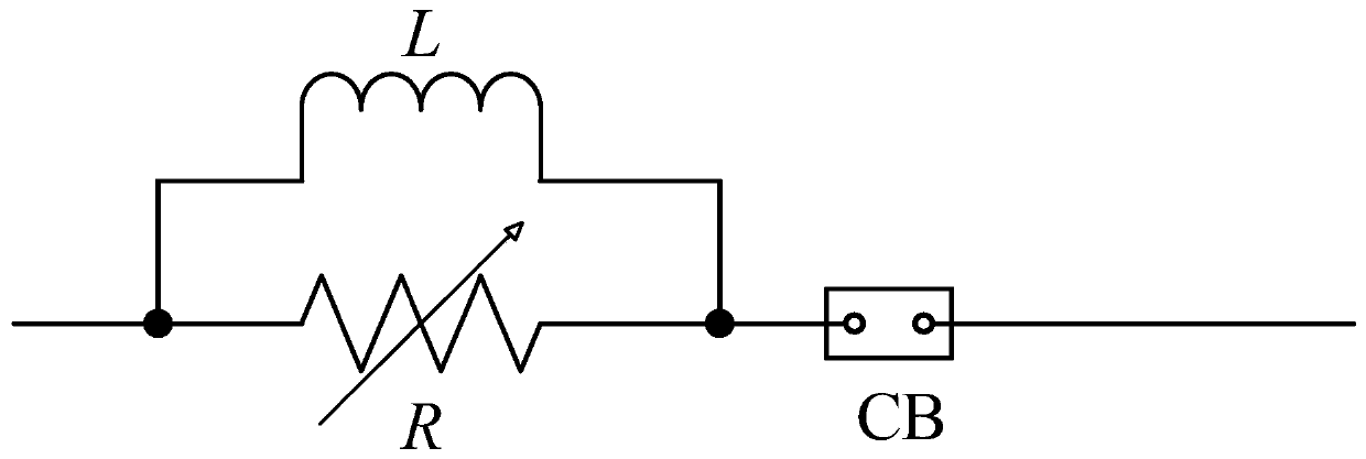
[0044] A novel self-driven modular current-limiting device includes a high-voltage rheostat R, a reactor L8, and a circuit breaker CB. After the high-voltage rheostat R and the reactor L8 are connected in parallel, they are connected in series with the circuit breaker CB.

[0045] The operation mode of the new self-driven modular current limiting device is:

[0046] (3) During normal operation, the circuit breaker CB is closed, and the resistance value of the high-voltage rheostat R is the smallest, close to zero resistance, bearing the system current, and the loss of the current limiting device is very small;

[0047] (4) When a fault occurs, the resistance of the high-voltage rheostat increases rapidly, and the current is gradually transferred to the L8 branch of the reactor, thereby limiting the rising rate and peak value of the fault current. At the same time, the circuit breaker opens to break the fault current after the current limit.

[0048] The technical scheme of the...

Embodiment 2

[0069] Figure 4 It consists of 12 5kV / 20kA self-driven variable impedance modules in parallel with 2 series to form a self-driven DC FCL. If it is used in a DC 10kV / 120kA system, the rated voltage of each module is 5kV, and the volume of the metal slider is reduced by one-third First, while the short-circuit current is the same, the electromagnetic force remains unchanged, the speed of the slider can be greatly increased, and the insulation requirements of the module will also be reduced.

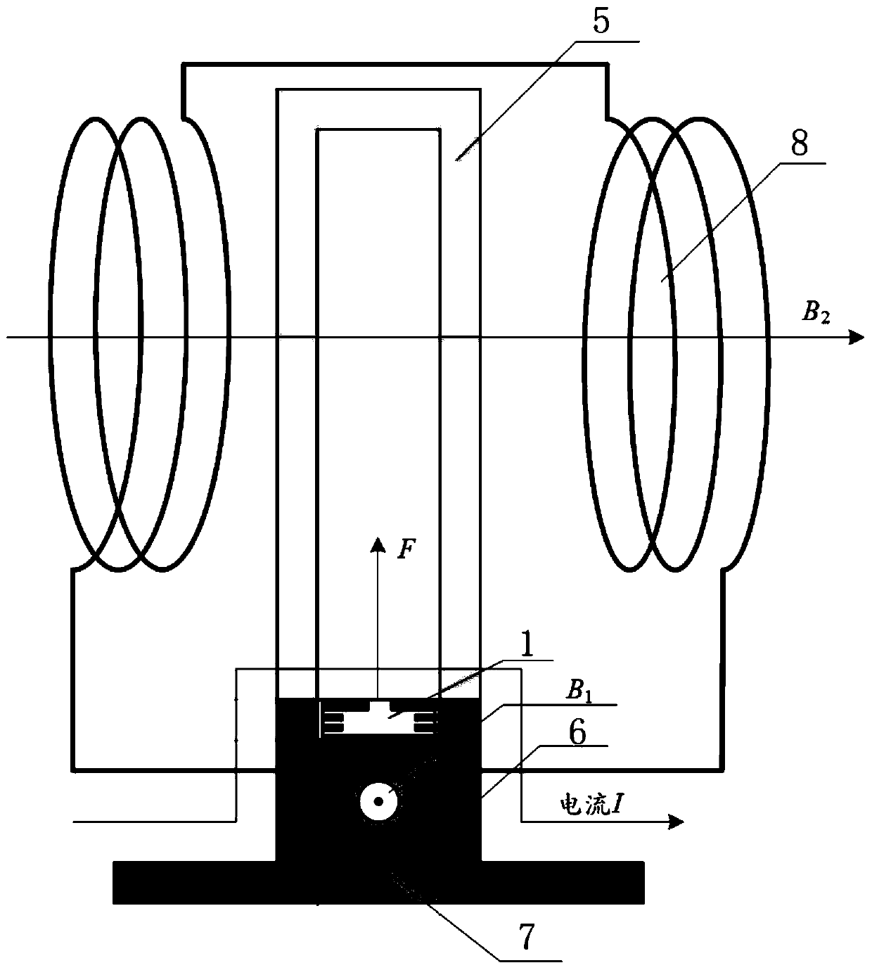
[0070] The characteristics of the self-driven variable impedance module proposed by the present invention are:

[0071] (1) The resistance value can change continuously from zero to a larger value;

[0072] (2) It can withstand large current and high voltage for a short time (its working condition is close to the closing resistance of high-voltage circuit breaker, so ZnO ceramic resistance can be selected);

[0073] (3) No need for detection and control devices, self-driven, quick respon...


PUM


Abstract

The invention belongs to the technical field of power transmission and distribution network fault current limiting, and relates to a novel self-driven modular current limiting device, which comprisesan electric reactor L, a circuit breaker CB and a high-voltage rheostat R, wherein the high-voltage rheostat R is connected with the electric reactor L in parallel and then connected with the circuitbreaker CB in series, a ceramic resistor is in a door shape, a sliding rail is arranged on the inner side of the ceramic resistor, the lower end of the ceramic resistor is connected with L-shaped electrodes, the electrodes on the two sides of the ceramic resistor are parallel and perpendicular to a liquid metal sliding block, the liquid metal sliding block is arranged between the electrodes, an insulating piece is arranged at the lower end of the liquid metal sliding block, And the electrodes on the two sides are connected with the two ends of the electric reactor L respectively, so that the high-voltage variable resistor R and the electric reactor L are connected in parallel. According to the invention, the self-driven variable impedance module is a resistive load, so that overvoltage andinrush current cannot be generated in the current limiting and conversion process; and the self-driven variable impedance module and the current-limiting reactor are convenient for modular design, and can be flexibly connected in series and in parallel according to application occasions.

Description

technical field [0001] The invention belongs to the technical field of fault current limiting in power transmission and distribution networks, and relates to a novel self-driven modular current limiting device. Background technique [0002] The root cause of the short-circuit current in the power system is the sudden drop in impedance, which causes the system impedance to be too low, causing the short-circuit current to exceed the standard or rise rapidly. The principle of limiting the short-circuit current is mainly to prevent the system impedance from being too low and to compensate for the sudden drop of impedance in time. Therefore, it is necessary to use a fault current limiter (Fault Current Limiter, FCL) device to limit the rising rate or stable value of the fault current to ensure that the fault current can be cut off reliably. [0003] The current FCL mainly achieves the purpose of current limiting by changing the impedance of the components that have been connecte...

Claims


Application Information

Patent Timeline
Patent Type & Authority Applications(China)
IPC IPC(8): H02H9/02H02H3/08H01H3/28
CPCH01H3/28H02H3/08H02H9/02
Inventor 廖敏夫黄智慧段雄英邹积岩
Owner DALIAN UNIV OF TECH
Why Eureka
Try Eureka