Electric meter and overload protection device for electric meter

An overload protection and electric meter technology, applied in the direction of measuring devices, measuring electrical variables, instruments, etc., can solve the problems of complex structure of overload protection devices, and achieve the effect of increasing movement and speed stroke, increasing wind power, and improving performance and life.

Active Publication Date: 2021-04-09
宁夏隆基宁光仪表股份有限公司
View PDF8 Cites 5 Cited by
  • Summary
  • Abstract
  • Description
  • Claims
  • Application Information

AI Technical Summary

Problems solved by technology

[0004] Based on the technical problem of the complex structure of the existing overload protection devi...

Method used


Image

  • Electric meter and overload protection device for electric meter
  • Electric meter and overload protection device for electric meter
  • Electric meter and overload protection device for electric meter

Examples


Embodiment 1

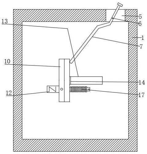
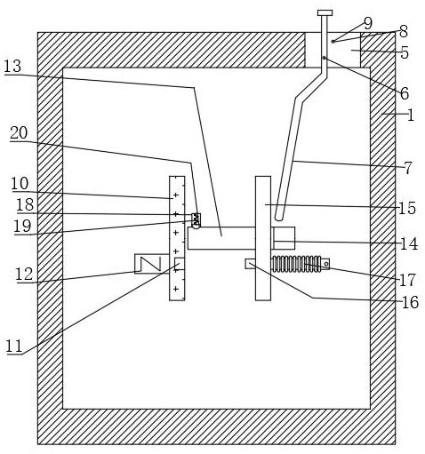
[0028] refer to Figure 1-4 , an electric meter and an overload protection device for the electric meter, comprising a housing 1, a first sliding groove 13 is opened on the inner wall of the rear end of the housing 1, a first sliding block 14 is slidably connected to the first sliding groove 13, the first sliding The front end of the block 14 is fixed with a second mounting plate 15 by bolts, and a second electrode sheet 16 is fixed through the inner side of the second mounting plate 15. A conductive coil 17 is arranged on the second electrode sheet 16, and a second Two grooves 18, the top of the inner wall of the second groove 18 is fixed with a second spring 19 by bolts, the bottom of the second spring 19 is fixed with a second block 20 by bolts, the cross section of the second block 20 is arranged in an arc shape, and the first slide The top of the block 14 and the contact position of the second block 20 are provided with a matching second card slot, the inner wall of the r...

Embodiment 2

[0035] refer to Figure 1-5 , an electric meter and an overload protection device for the electric meter. The inner wall of the rear end of the casing 1 is provided with a second slide slot 22, and a second slide block 24 is slidably connected to the second slide slot 22. The front end of the second slide block 24 is connected to the permanent The magnets 12 are bonded and fixed, the bottom of the permanent magnet 12 is bonded with a tooth plate 25, and the inner wall of the rear end of the housing 1 is connected with a first pole and a second pole through bearing rotation, and the first pole and the second pole are connected to each other. A gear 26 and a worm wheel 27 are sheathed and fixed respectively, and the gear 26 and the worm wheel 27 are meshed and connected, and a heat dissipation mechanism is arranged in the housing 1 .

[0036] In the present invention, the heat dissipation mechanism is fixed with a support rod 28 by bolts at the bottom of the inner wall of the ho...


PUM


Abstract

The invention belongs to the technical field of overload protection devices, particularly relates to an electric meter and an overload protection device for the electric meter, and provides the following scheme for solving the problem that an existing overload protection device is complex in structure: the electric meter comprises a shell, a first sliding groove is formed in the inner wall of the rear end of the shell, and a first sliding block is slidably connected in the first sliding groove; a second mounting plate is fixed to the front end of the first sliding block, and a second electrode plate is fixed to the inner side of the second mounting plate; a second spring is fixed to the top of the inner wall of the second groove, and a second clamping block is fixed to the bottom of the second spring; a first mounting plate is fixed to the inner wall of the rear end of the shell, and a first electrode plate is embedded and fixed to the inner side of the first mounting plate; and a permanent magnet is adhered to one side of the first mounting plate. According to the invention, the magnetic field force on the second electrode plate and the permanent magnet interact with each other, so that the first sliding block relieves the constraint of the second clamping block and moves rightwards, the first electrode plate and the second electrode plate are separated from contact, a circuit is cut off, and the circuit and an electric appliance are protected.

Description

technical field [0001] The invention relates to the technical field of overload protection devices, in particular to an electric meter and an overload protection device for the electric meter. Background technique [0002] Today's electric power technology is developing rapidly, and the electric meter is inseparable from the process of electric power transmission and use. The electric meter is the abbreviation of the electric energy meter. , The emergence of home appliances has brought about earth-shaking changes in people's lives. Home appliances need to be powered on to work, which requires the use of a power supply. When the current inside the wire is at a normal value, the power supply can normally supply power to household appliances. When the current passing through the wire is at an abnormal value, the power supply cannot normally supply power to household appliances, and if it is serious, it will cause the power supply to burn and explode. [0003] In order to solve...

Claims


Application Information

Patent Timeline
IPC IPC(8): G01R11/04G01R11/16
CPCG01R11/04G01R11/16
Inventor 任嘉豪李旋黄守栋
Owner 宁夏隆基宁光仪表股份有限公司
Why Eureka
Try Eureka