Control valve device for variable capacity type swash plate compressor

a control valve and compressor technology, which is applied in the direction of pump control, positive displacement liquid engine, and electric motor with armature, etc., can solve the problems of non-uniform sliding resistance of the operating rod with respect to the fixed core, inability to avoid the generation of radial electromagnetic force, and increase of undesired radial electromagnetic force, etc., to achieve prevent non-uniform abrasion of the operating rod and maintain stable opening/closing operation of the control valv

Inactive Publication Date: 2007-09-25
SANDEN CORP
View PDF31 Cites 6 Cited by
  • Summary
  • Abstract
  • Description
  • Claims
  • Application Information

AI Technical Summary

Benefits of technology

[0013]An object of the present invention is to provide a control valve device for a variable capacity type swash plate compressor, which prevents non-uniform abrasion of an operating rod in a capacity control valve thereof and which is capable of maintaining stable opening / closing operation of the control valve.
[0023]In this case, since the valve member of the valve unit operates by a slight difference between the axial electromagnetic force and the urging force, by reducing the urging force of the valve spring, the axial electromagnetic force to be generated by the magnetic circuit can be reduced. Therefore, even when the magnetic circuit generates the above-mentioned radial electromagnetic force, the radial electromagnetic force is small, and smooth sliding of the operating rod is assured with respect to the fixed core. As a result, the abrasion of the operating rod is reduced, and the valve unit stably operates over a long period.
[0025]In this case, when the differential pressure increases the magnetic gap, the magnetic resistance of the magnetic circuit increases, and the axial electromagnetic force of the magnetic circuit is reduced. On the other hand, when the differential pressure reduces the magnetic gap, the axial electromagnetic force of the magnetic circuit increases.
[0028]Furthermore, the resistance variable mechanism can further include a spacer disposed on the operating rod between the fixed core and the movable member, and this spacer is made of a nonmagnetic material, and defines a minimum value of the magnetic gap. Since the spacer constantly secures the magnetic gap between the fixed core and the movable member, the movable member can securely receive the differential pressure.
[0030]Preferably the control valve is inserted in the introducing passage, and the valve spring urges the valve member in the opening direction. In this case, during stop of the operation of the air conditioning system, no current is supplied to the electromagnetic solenoid assembly, and the valve unit is maintained in an open position. Therefore, the discharge chamber is connected to the crank chamber, and the pressure in the crank chamber rises. This pressure rise reduces the tilt angle of the swash plate, that is, the discharge capacity of the compressor. As a result, an energy required for driving the compressor is saved.

Problems solved by technology

However, the magnetic circuit generates not only the axial electromagnetic force but also a radial electromagnetic force along a radial direction of the movable core because of a processing or assembling error of each component of the electromagnetic solenoid assembly, and the generation of the radial electromagnetic force cannot be avoided.
Moreover, with the increase of the axial electromagnetic force, an undesired radial electromagnetic force also increases.
Since the large radial electromagnetic force biases the movable core in a radial direction, a sliding resistance of the operating rod with respect to the fixed core is not uniform in a peripheral direction of the operating rod.
Therefore, abrasion of the outer peripheral surface of the operating rod proceeds only partially in the peripheral direction, this non-uniform abrasion obstructs stable sliding of the operating rod, and results in unstable opening / closing operation of the valve member in the valve unit.

Method used


Image

  • Control valve device for variable capacity type swash plate compressor
  • Control valve device for variable capacity type swash plate compressor
  • Control valve device for variable capacity type swash plate compressor

Examples


Embodiment Construction

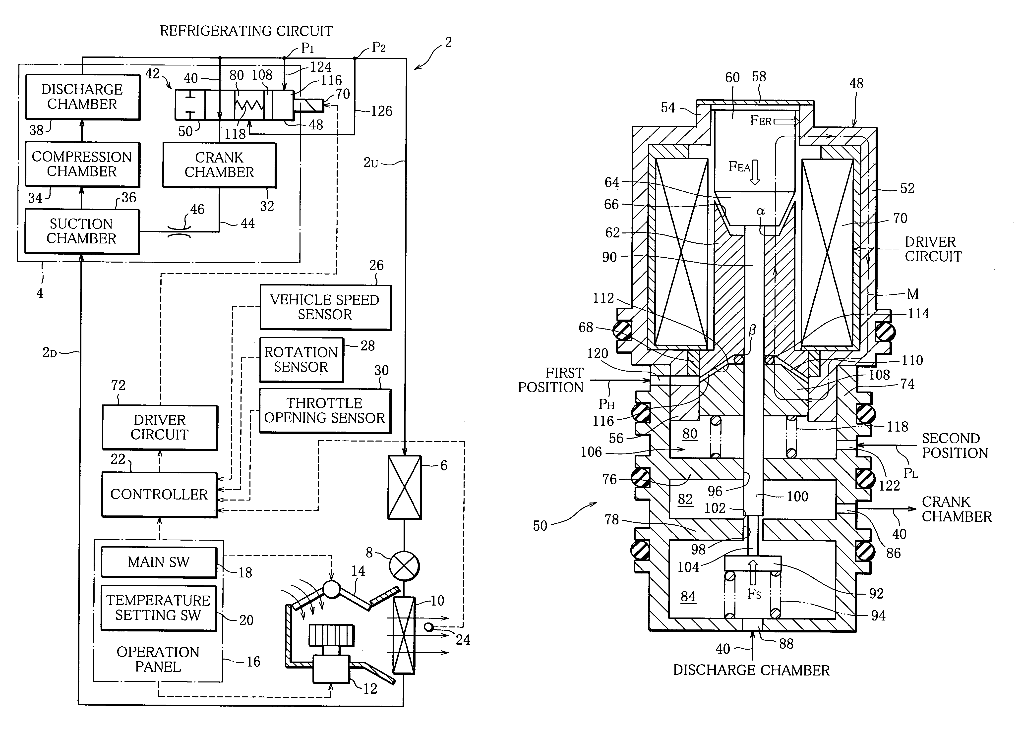
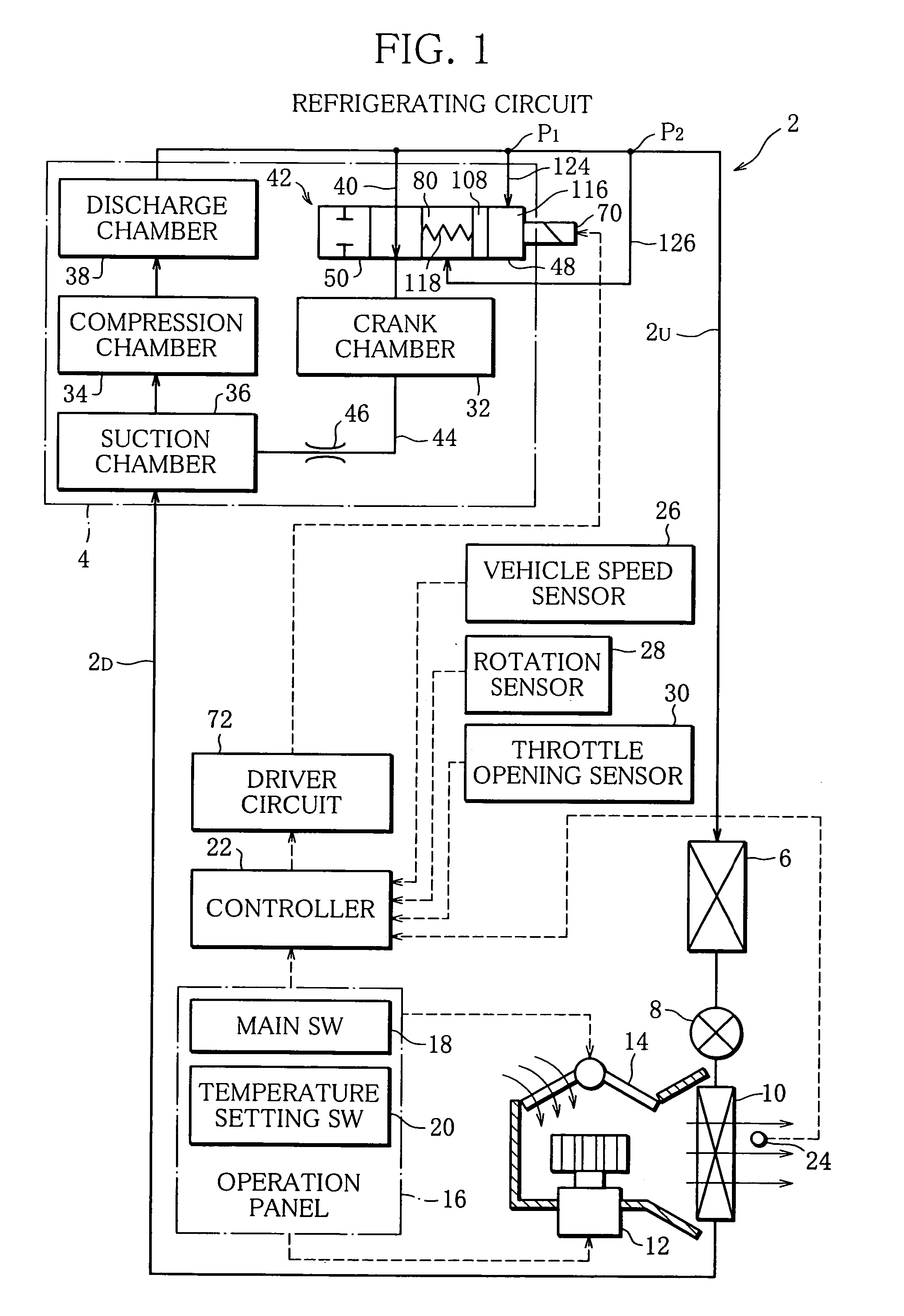
[0036]As shown in FIG. 1, an air conditioning system of a vehicle includes a refrigerating circuit and the refrigerating circuit includes a circulation path 2 of a refrigerant. In this circulation path 2, a variable capacity type swash plate compressor 4, a condenser 6, an expansion valve 8 and evaporator 10 are arranged in this order.

[0037]The compressor 4 compresses the refrigerant, and discharges the compressed refrigerant toward the condenser 6. The condenser 6 condenses the supplied high-pressure refrigerant, and the liquefied refrigerant is supplied to the evaporator 10 through the expansion valve 8. The liquefied refrigerant is vaporized in the evaporator 10, and air around the evaporator 10 is cooled. Thereafter, the vaporized refrigerant is sucked into the compressor 4, and again compressed to circulate in the circulation path 2.

[0038]In order to introduce the cooled air into a passenger room of the vehicle, an air blower 12 and damper 14 are disposed in the vicinity of the...


PUM

PropertyMeasurementUnit
pressureaaaaaaaaaa
electromagnetic forceaaaaaaaaaa
magnetic resistanceaaaaaaaaaa

Abstract

There is disclosed a control valve device for a variable capacity type swash plate compressor for use in an air conditioning system. The device comprises an introducing passage for connecting a discharge chamber to a crank chamber in the compressor, and a control valve for adjusting a pressure in the crank chamber in an autonomous manner to control a discharge capacity of the compressor. The control valve includes a valve unit for opening / closing the introducing passage and an electromagnetic solenoid assembly for operating the valve unit. The control valve device further comprises a resistance variable mechanism for varying a resistance of the magnetic circuit in the assembly in accordance with a differential pressure of the refrigerant between two points defined between the compressor and a condenser of the system.

Description

[0001]This Nonprovisional application claims priority under 35 U.S.C. 119(a) on patent application Ser. No. 2003-090598 filed in Japan on Mar. 27, 2003, the entire contents of which are hereby incorporated by reference.BACKGROUND OF THE INVENTION[0002]1. Field of the Invention[0003]The present invention relates to a control valve device for a variable capacity type swash plate compressor, and the compressor is used in a refrigerating circuit of an air conditioning system disposed in a vehicle.[0004]2. Description of the Related Art[0005]A refrigerating circuit includes an evaporator and a condenser, and a variable capacity type swash plate compressor is disposed between the evaporator and condenser. This type of compressor is described, for example, in Japanese Unexamined Patent Publication No. 2001-107854. This known compressor has a crank chamber, and a swash plate is rotatably accommodated in the crank chamber. A tilt angle of the swash plate determines a discharge capacity of a ...

Claims


Application Information

Patent Timeline
Patent Type & Authority Patents(United States)
IPC IPC(8): F04B1/26F04B49/06F04B27/14F04B27/18H01F7/08H01F7/13H01F7/16
CPCF04B27/1804F04B2027/1827F04B2027/185F04B2027/1854F04B2205/05
Inventor OCHIAI, YOSHIHIRO
Owner SANDEN CORP
Why Eureka
Try Eureka