Discharge lamp lighting apparatus

a technology of lighting apparatus and discharge lamp, which is applied in the direction of electric variable regulation, process and machine control, instruments, etc., can solve the problems of short life of discharge lamp, prevent abrasion of discharge lamp electrodes, suppress discharge lamp overcurrent, prolong discharge lamp life

Inactive Publication Date: 2009-01-15
MINEBEA CO LTD
View PDF2 Cites 3 Cited by
  • Summary
  • Abstract
  • Description
  • Claims
  • Application Information

AI Technical Summary

Benefits of technology

[0017]With the structure according to the present invention, the overcurrent flowing to the discharge lamp can be suppressed and the abrasion of an electrode in the discharge lamp is prevented, thereby extending the lifetime of the discharge lamp. Further, the discharge lamp lighting apparatus with low costs and compact size can be provided.

Problems solved by technology

A conventional discharge lamp lighting apparatus, such as the discharge lamp lighting apparatus 100 shown in FIG. 5, has a problem that the overcurrent causes the abrasion of an electrode in the discharge lamp and the lifetime of the discharge lamp thus becomes short.

Method used


Image

  • Discharge lamp lighting apparatus
  • Discharge lamp lighting apparatus
  • Discharge lamp lighting apparatus

Examples


Embodiment Construction

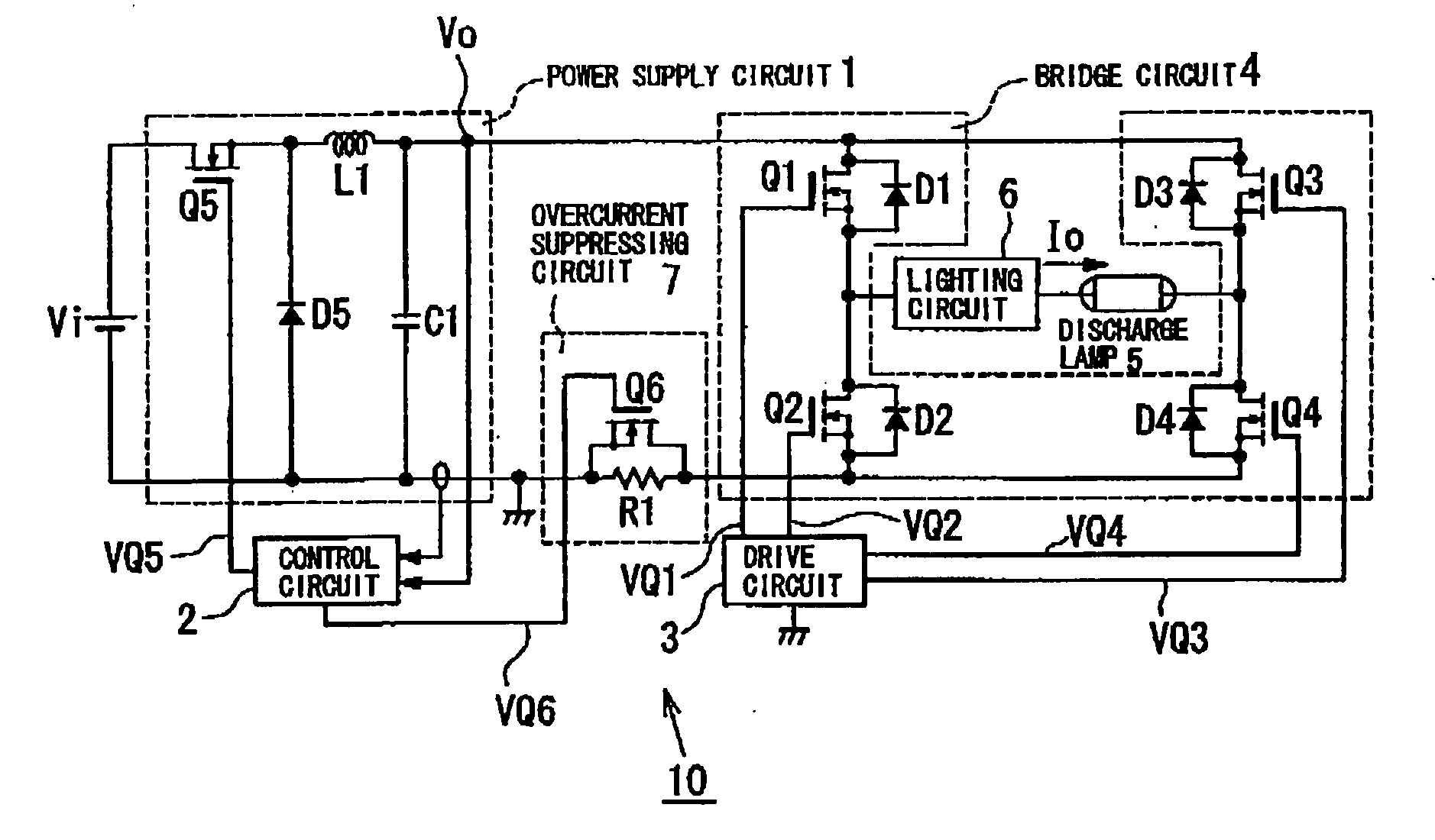
[0038]Hereinbelow, an embodiment of the present invention will be described with reference to the drawings. FIG. 1 is a circuit structure diagram showing a discharge lamp lighting apparatus 10 according to the embodiment of the present invention. Referring to FIG. 1, the discharge lamp lighting apparatus 10 comprises: an input power supply Vi that supplies DC current to the discharge lamp lighting apparatus 10; a power supply circuit 1 that drops an output voltage of the input power supply Vi and outputs the voltage; a bridge circuit 4 that applies an output voltage of the power supply circuit 1 to a discharge lamp 5 by switching the polarity of the output voltage of the power supply circuit 1 to perform AC operation of the discharge lamp 5; a lighting circuit 6 that starts the discharge lamp 5; a control circuit 2 that controls the power supply circuit 1 and a overcurrent suppressing circuit 7, which will be described later; and a drive circuit 3 that drives the bridge circuit 4. T...


PUM


Abstract

A discharge lamp lighting apparatus includes an input power supply, a power supply circuit, a bridge circuit having switching elements Q1 to Q4 that performs AC operation of a discharge lamp, a lighting circuit, a control circuit that controls the power supply circuit, and a drive circuit that drives bridge circuit. An overcurrent suppressing circuit having a resistance element and a switching element connected to the resistance element in parallel therewith is connected between the negative side of the bridge circuit and the negative side of the power supply circuit, so that the overcurrent suppressing circuit automatically adjusts current flowing to the switching elements and suppresses the overcurrent upon starting the discharge lamp.

Description

TECHNICAL FIELD[0001]The present invention relates to a discharge lamp lighting apparatus, and more particularly, to a discharge lamp lighting apparatus that prevents overcurrent flowing to a high-intensity discharge lamp, such as a high-pressure mercury lamp, a high-pressure sodium lamp, and a metal halide lamp, upon starting lighting operation of the high-intensity discharge lamp.BACKGROUND ART[0002]Conventionally, as a lighting apparatus that lights a high-intensity discharge lamp, such as a high-pressure mercury lamp, a high-pressure sodium lamp, and a metal halide lamp, a discharge lamp lighting apparatus shown in FIG. 5 is well known. Referring to FIG. 5, a discharge lamp lighting apparatus 100 comprises: an input power supply Vi that supplies a DC voltage to the discharge lamp lighting apparatus 100; a power supply circuit 1 that reduces an output voltage of the input power supply Vi and outputs the resultant voltage; a bridge circuit 4 that applies an output voltage Vo of th...

Claims


Application Information

Patent Timeline
Patent Type & Authority Applications(United States)
IPC IPC(8): H05B41/36
CPCH02M1/32Y02B20/208H05B41/2928H02M2001/007H02M1/007Y02B20/00
Inventor YAMASHITA, MASAYA
Owner MINEBEA CO LTD
Why Eureka
Try Eureka