Supercharger

a supercharger and supercharger technology, applied in the direction of machines/engines, bearing unit rigid support, manual lubrication, etc., can solve the problems of affecting the performance of the engine, so as to improve heat resistance and heat resistance. , the effect of high damping efficiency

Inactive Publication Date: 2008-04-10
JTEKT CORP
View PDF19 Cites 2 Cited by
  • Summary
  • Abstract
  • Description
  • Claims
  • Application Information

AI Technical Summary

Benefits of technology

[0014] According to this configuration, since the damper member is formed by knitting the metal wire, the damper member can elastically deform (shrink) entirely, and so the vibration can be attenuated in a three dimensional and omnidirectional manner and a high damping efficiency can be attained. Further since the damper member is formed by the metal wire, heat resisting properties can be improved, and so the damper member is suitable for a damper member of a supercharger which temperature becomes quite high. Further, by using such the damper member, the oil film damper is not required to be used unlike the related art and so various problems caused by supplying the engine oil to the oil film damper can be eliminated.
[0015] Preferably, gaps are formed among the wires and lubricant is filled into the gaps. Thus, the abrasion of the wires due to the mutual rubbing of the wires caused by the elastic deformation of the damper member can be prevented.
[0016] Preferably, the housing has a tank portion for reserving lubricant for the bearing and a supply means for supplying the lubricant within the tank portion to the bearing. According to this configuration, it becomes not necessary to supply the engine oil for lubricating the bearings as well as for the damper of the turbine shaft, whereby the housing can be simplified in its configuration and reduced in its cost.
[0017] In other words, even if an oil path for the engine oil for lubricating the bearings is not formed at the housing, the vibration of the turbine shaft can be reduced by using the damper member according to the invention.
[0018] According to the invention, the vibration of the turbine shaft can be reduced suitably without using the engine oil.

Problems solved by technology

Thus, energy loss of the engine becomes large and so the efficiency degrades.
Thus, the configuration of the housing etc. becomes complicated and the manufacturing cost increases.
Further, since the engine oil degrades gradually in accordance with the use thereof, there arises a problem that the efficiency of the oil film damper also degrades due to the degradation of the engine oil.
Thus, the contaminating material contained in the engine oil may be supplied to the bearings to badly influence on the durability of the bearings.

Method used


Image

  • Supercharger
  • Supercharger
  • Supercharger

Examples


Embodiment Construction

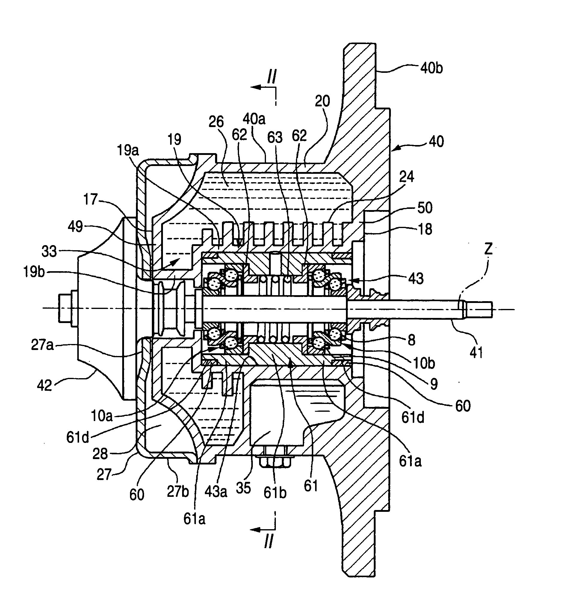
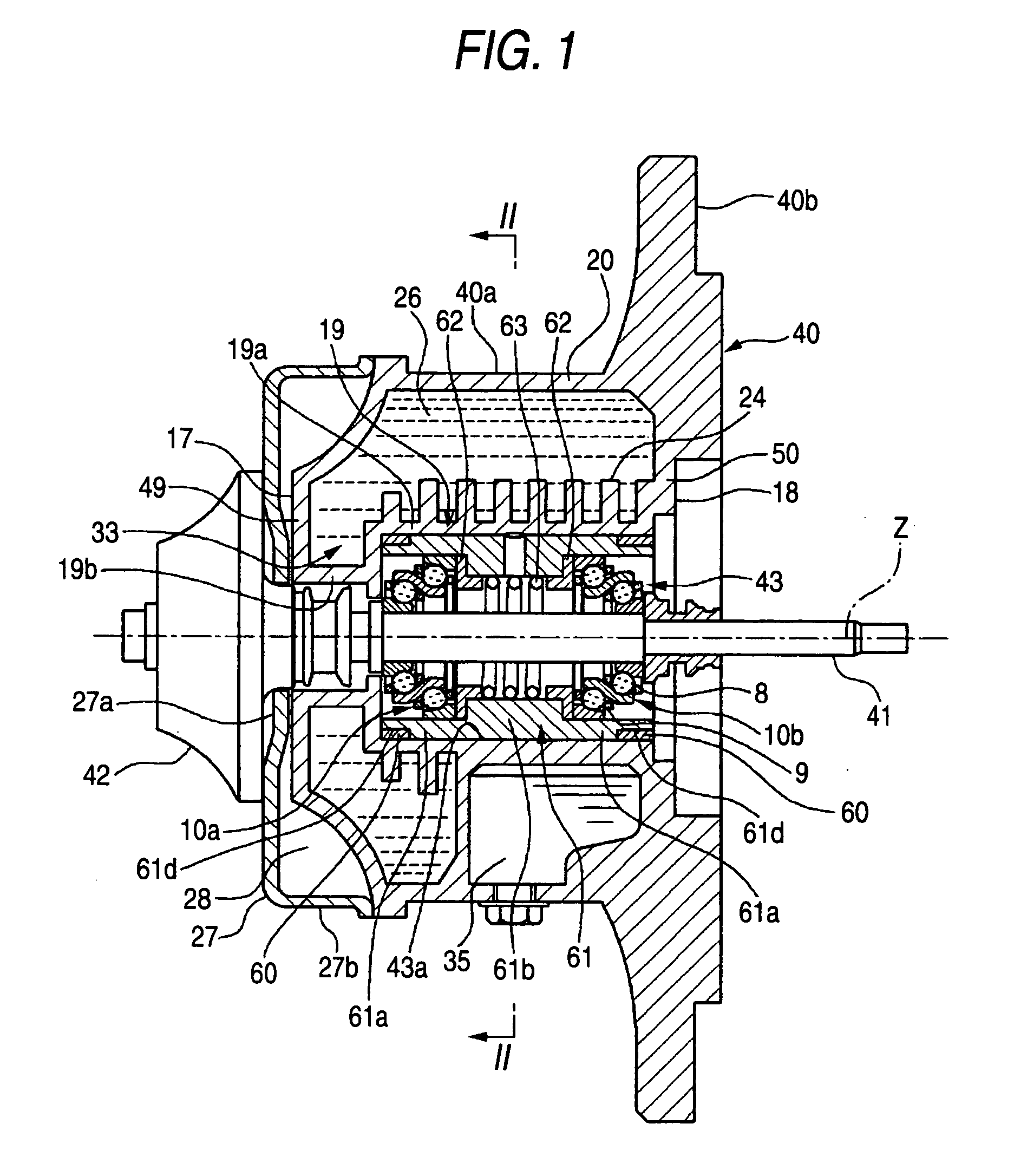
[0027]FIG. 1 is a sectional diagram showing an embodiment of a supercharger according to the invention. The supercharger includes a housing 40 and a turbine shaft 41 supported by the housing 40 via rolling bearings 10a, 10b within the housing 40. The both end portions of the turbine shaft 41 in the axial direction thereof protrude from the housing 40. A turbine 42 is provided at the one end portion of the turbine shaft 41 and a not-shown compressor is provided at the other end portion thereof. The supercharger is arranged for the engine of an automobile. A pair of the rolling bearings 10a and a pair of the rolling bearings 10b are provided at separately along a shaft center Z direction in a bearing supporting member 61 disposed inside the housing.

[0028] The housing 40 includes a main body portion 40a having an outer periphery of a cylindrical shape and a flange portion 40b extending outward in the radial direction from the outer peripheral portion of the end portion 50 of the main ...


PUM


Abstract

A turbine shaft to which a turbine is fixed is supported by a bearing supporting member via bearings so as to rotate freely. The bearing supporting member is supported by a housing via the damper member. The damper member is formed by knitting a wire made of metal.

Description

BACKGROUND OF THE INVENTION [0001] The present invention relates to a supercharger. [0002] In an automobile, a supercharger has been widely used since it can further improve the efficiency of an engine. The supercharger includes a housing and a turbine shaft which is supported via bearings within the housing. A turbine wheel is fixed at the one end of the turbine shaft and a compressor wheel is fixed to the other end thereof. [0003] The turbine shaft rotates at a high speed and so vibration occurs in accordance with the rotation thereof. Thus, a damper means is indispensable for the supporting portion of the turbine shaft in order to reduced the vibration. As a damper means of a related art, as disclosed in JP-A-4-72424 and JP-A-2001-303964, there is one which is configured in a manner that bearings for supporting a turbine shaft are attached to the inner peripheral surface of the a cylindrical oil film damper, engine oil is supplied between the outer peripheral surface of the oil f...

Claims


Application Information

Patent Timeline
Patent Type & Authority Applications(United States)
IPC IPC(8): F02B33/00F16N7/00
CPCF01D25/164F02B39/14F02B39/16F02C6/12F16C19/55F16C2360/24F05D2260/96F05D2250/131F05D2250/141F05D2300/6012F05D2220/40F16C19/181F16C19/548F16C27/04F16C35/077
Inventor UENO, HIROSHISHIRAKI, TOSHIHIKOOSHIMA, AKIONAKASHITA, TOMONORIOHTSUKI, MASAAKIBANDO, SHIGENORIABE, MASAKINAKATA, RYUJIKIDA, TAKEHISA
Owner JTEKT CORP
Why Eureka
Try Eureka