Shock absorber for a transportation means

a technology for transportation means and shock absorbers, which is applied in the direction of shock absorbers, braking systems, transportation and packaging, etc., can solve the problems of insufficient increase of force counteracting, and achieve the effects of increasing resistance, avoiding auto-oscillation and resonance regime, and increasing damping efficiency

Inactive Publication Date: 2012-04-03
TROJA KEHPITAL GRUPP KORP
View PDF12 Cites 5 Cited by
  • Summary
  • Abstract
  • Description
  • Claims
  • Application Information

AI Technical Summary

Benefits of technology

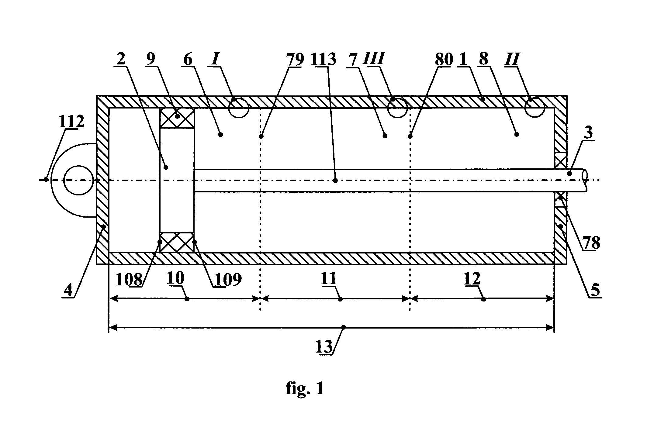
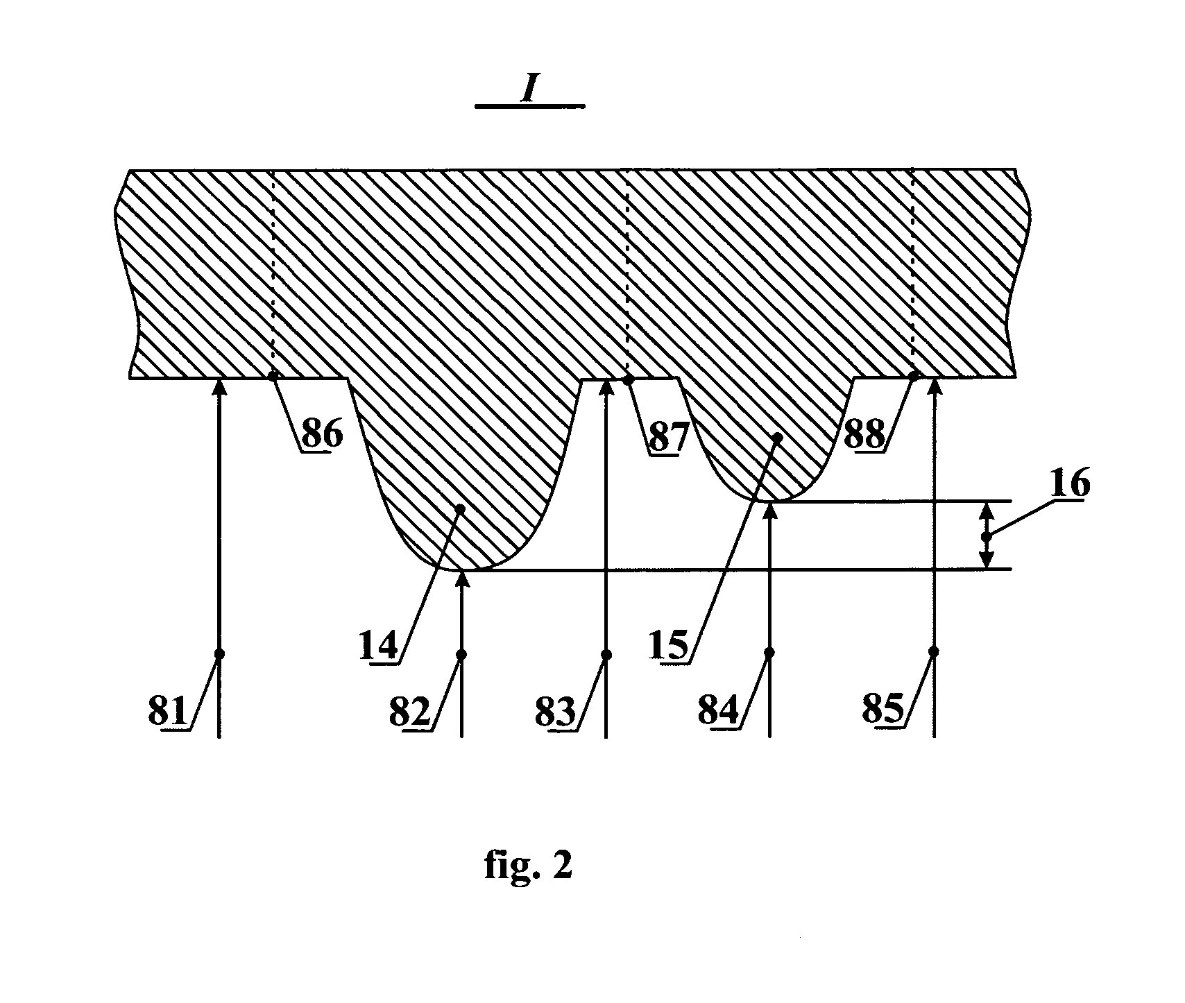
[0008]The aforementioned aims have been achieved by providing an inventive shock absorber that generally comprises a sleeve, a cylindrical piston with a seal attached to the cylindrical surface of piston with two side surfaces, a rod coupled with the piston, a piston cap closing the sleeve on the piston's side, and a rod cap closing the sleeve on the rod's side. The piston and rod move within the sleeve overcoming resistance of oil / gas cross-flows from one sleeve's chamber to the other, friction between the seal and the sleeve's walls, and friction between the rod and a seal mounted in the rod cap. The proposed shock absorber allows increasing the resistance offered to the movement of piston thereby improving the efficiency of damping. This is achieved by providing a number of narrowing / widening necks arranged on the sleeve's internal walls within regions adjoined to the caps. Different embodiments combine features conditioned by various diameter differences for the necks, etc. Several embodiments introduce asymmetry in the design of shock absorber and thereby insure suppressing / avoiding auto-oscillation and resonance regimes.

Problems solved by technology

A drawback of such device is an insufficient increase of a force counteracting the movement of piston in the cylinder within the region(s) proximate to the absorber's cap(s).

Method used


Image

  • Shock absorber for a transportation means
  • Shock absorber for a transportation means
  • Shock absorber for a transportation means

Examples


experiment 1

[0152]The sleeve of the first shock absorber was made according to the prototype. The sleeve of the shock absorber was furnished with a narrowing neck 47, shaped as an element of a circle, which was arranged on the inner surface of a sleeve 46. A length 53 of this element was 50 micrometers, and a reduction of the sleeve's radius 54 was 50 micrometers. A compound piston seal TPS / T was utilized for the shock absorber. It's worth to note that the design of the prototype was also associated with narrowing sleeves, wherein the narrowing section had a length of several millimeters, whereas the inventive sleeves have the length of narrowing sections not exceeding 100 micrometers.

[0153]FIG. 12 shows a sleeve 46, and a portion of the piston with a seal 48. The piston moves towards the direction indicated by a pointing arrow 49, wherein a side surface 111 of the seal 48 faces forward. FIG. 12 also shows a graph located under the picture, which graph illustrates a dependency of a force ‘P’, c...

experiment 2

[0156]The second experiment is illustrated on FIG. 13. The inner surface of a sleeve 57 had two narrowing necks shaped as semi-circles with a width 55 of 100 micrometers equal for both the necks. The distance 56 between the necks 55 was chosen of 50 micrometers. The difference 58 between the radiuses of the necks amounted to 50 micrometers.

[0157]A sleeve 57 is depicted on FIG. 13. The piston 46 having the seal 48 with the side surface 111 are shown on FIG. 12. The piston moves forward, overcoming the resistance of the narrowing necks. FIG. 13 contains a graph located below the picture. The graph illustrates a dependency of a force ‘P’, counteracting the movement of the piston in the sleeve, upon a coordinate ‘1’ of the right side surface 111 of the seal.

[0158]During the movement of piston along the section with the greater diameter, force P had a value of 5 Newton (that corresponds to a level 59 on the graph). During the overcoming the narrowing necks, there were two surges of force...

experiment 3

[0161]The third experiment is illustrated on FIG. 14. The shock absorber comprises a sleeve 63 and a piston (not shown) with a seal 48 having two seal surfaces 110 and 111 (shown on FIG. 12). The sleeve 63 has two narrowing necks, formed by elements outstanding from the sleeve's walls and having a trapezium-like shape (as shown on FIG. 14). The length of each such narrowing neck (summarizing sections 64, 65, and 66) constitutes 150 micrometers. The distance 67 between the two necks is 50 micrometers. As in the previous experiment, the radius difference is 50 micrometers.

[0162]FIG. 14 reflects the movement of piston from the left to the right, i.e. the side surface 111 faces the direction of movement, overcoming the narrowing necks. A graph located under the picture on FIG. 14 shows a dependency of force ‘P’, counteracting the movement of the piston, upon coordinate ‘1’ of the surface 111.

[0163]During the movement of the piston in the piston's section with a greater diameter, force P...


PUM


Abstract

A shock absorber comprises a sleeve, a cylindrical piston with a seal attached to the cylindrical surface of piston with two side surfaces, a rod coupled with the piston, a piston cap enclosing the sleeve on the piston's side, and a rod cap enclosing the sleeve on the rod's side. The piston and rod move within the sleeve overcoming resistance of oil / gas cross-flows from one sleeve's chamber to the other, friction between the seal and the sleeve's walls, and friction between the rod and a seal mounted in the rod cap. The proposed absorber allows increasing the resistance offered to the movement of piston thereby improving the efficiency of damping, and suppressing / avoiding auto-oscillation and resonance regimes. This is achieved by providing a number of narrowing / widening necks arranged on the sleeve's walls within regions adjoined to the caps. Different embodiments combine features conditioned by various diameter differences for the necks, etc.

Description

FIELD OF THE INVENTION[0001]The invention relates to the machine construction field, more specifically to the field of designing dampers (shock absorbers) or struts mostly for transportation means. It might be particularly utilized for manufacturing hydraulic, pneumo-hydraulic, and pneumatic shock absorbers applicable, for example, for support of frame elements of a transportation means.BACKGROUND OF THE INVENTION[0002]Although there are known a great variety of dampers or shock absorbers, a majority thereof typically comprise common elements: a sleeve (cylinder) having a longitudinal axis and filled with suitable oil, a damper piston (herein further called ‘piston’), and a piston rod (herein further called ‘rod’) fixedly coupled with the piston. The rod and piston are capable of accomplishing a reciprocating movement within the sleeve along the longitudinal axis thereof. Besides the aforementioned elements, a shock absorber can include a housing, typically enclosing the sleeve, and...

Claims


Application Information

Patent Timeline
Patent Type & Authority Patents(United States)
IPC IPC(8): B60T7/12F16F9/30
CPCF16F9/3242F16F9/48
Inventor TIKHONENKO, OLEG OLEGOVICHLOBKO, VLADIMIR PAVLOVICH
Owner TROJA KEHPITAL GRUPP KORP
Why Eureka
Try Eureka