A wide field of view radioactive source positioning system and positioning method
What is Al technical title?
Al technical title is built by PatSnap Al team. It summarizes the technical point description of the patent document.
A positioning system and radioactive source technology, applied in the field of nuclear radiation detection, can solve problems such as limited field of view for detecting radioactive sources, and achieve the effects of large imaging field of view, low production cost, and simple and fast positioning process
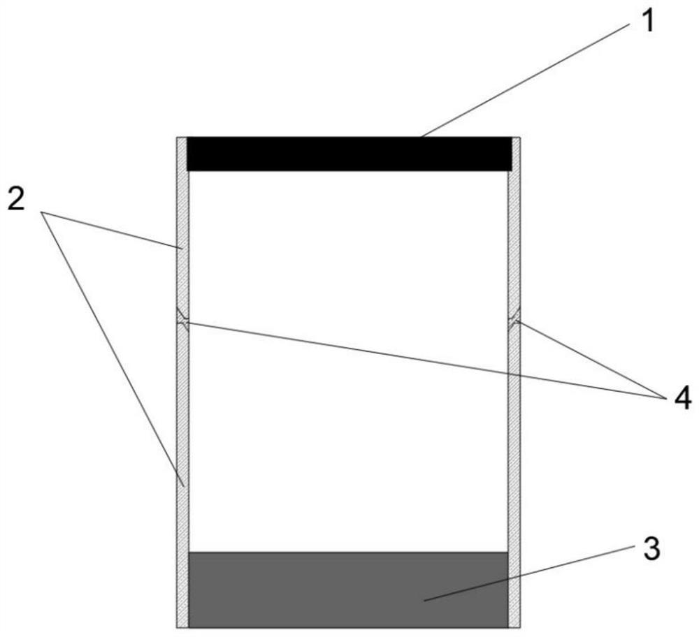
Active Publication Date: 2021-03-12
UNIV OF SCI & TECH BEIJING
View PDF12 Cites 0 Cited by
Summary
Abstract
Description
Claims
Application Information
AI Technical Summary
This helps you quickly interpret patents by identifying the three key elements:
Problems solved by technology
Method used
Benefits of technology
Problems solved by technology
[0004] The technical problem to be solved by the present invention is to provide a radioactive source positioning system and positioning method with a large field of view combined with small hole imaging, so as to solve the technical problem of limited field of view for detecting radioactive sources existing in the above coding hole imaging detection system
Method used
Image
Click on the blue label to locate the original text in one second.
Reading with bidirectional positioning of images and text.
Examples
Embodiment Construction
[0030] In order to make the technical problems, technical solutions and advantages to be solved by the present invention clearer, the following will describe in detail with reference to the drawings and specific embodiments.
PUM
Abstract
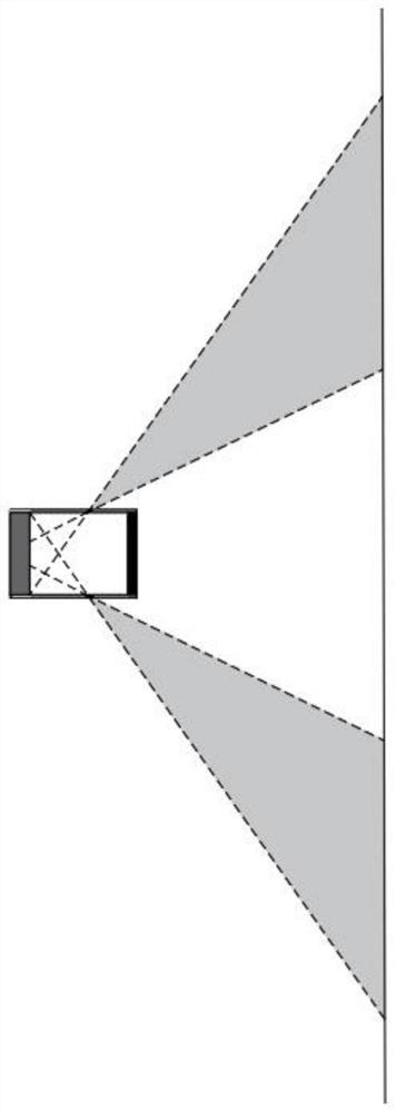
The invention provides a large-field radioactive source positioning system and a positioning method. The large-field radioactive source positioning system comprises a coding plate, a plurality of sideshielding layers and a gamma imaging detector; wherein the coding plate is used for accurately imaging a radioactive source. Imaging holes are equipped on the side shielding layers that encircle thegamma imaging detector, thereby forming a cylindrical shielding structure around the outside of the gamma imaging detector. The imaging holes on the side shielding layers are used to enlarge field ofthe detector, playing roles of imaging and early warning; the gamma imaging detector is used to process incident information of gamma rays,so as to obtain an image from the coding plate and an image from the imaging holes, the image from the coding plate and the image from the imaging holes are reconstructed and then detected to determine an incident angle of the gamma rays and a position of the radioactive source. The large-field radioactive source positioning system of the invention has a large imaging field of view and can avoid blind search. The side imaging holes are small and less sensitive without affecting imaging effect of the coding plate. The large-field radioactive source positioning system has low production cost, simple and rapid positioning process.
Description
technical field [0001] 本发明涉及核辐射探测技术领域,特别是指一种编码板结合小孔成像的大视野放射源定位系统及定位方法。 Background technique [0002] 探测伽马射线的核辐射定位仪对放射源的监测、定位及相关处理至关重要。随着科技的发展及放射源利用领域的扩大,人们对于探测器及探测系统的要求也随之提高。 [0003] 现有技术中,基于编码孔径成像技术的编码板探测器被广泛用于放射源的定位和监测,但这些探测器的成像视野范围有限,为精确获得放射源的具体位置,需不断调整探测角度,该过程往往耗时较长。虽然为扩大探测视野,可采用多个编码板探测器同时探测的方式,但此方法会增加成本且设备较为笨重。 Contents of the invention [0004] 本发明要解决的技术问题是提供一种编码板结合小孔成像的大视野放射源定位系统及定位方法,以解决上述编码孔成像探测系统中存在的探测放射源视野受限的技术问题。 [0005] 为解决上述技术问题,本发明提供一种大视野放射源定位系统,所述大视野放射源定位系统包括:编码板、多个侧边屏蔽层和伽马成像探测器;其中,每一侧边屏蔽层上分别开设有成像孔,所述多个侧边屏蔽层环绕所述伽马成像探测器设置,在所述伽马成像探测器外侧围成一筒状屏蔽结构,以使通过所述成像孔入射的伽马射线入射到所述伽马成像探测器上; [0006] 所述编码板和所述伽马成像探测器分别位于所述筒状屏蔽结构的两端,以使通过所述编码板入射的伽马射线入射到所述伽马成像探测器上; [0007] 所述伽马成像探测器用于处理通过所述编码板及成像孔入射的伽马射线入射信息,以通过所述编码板或成像孔对放射源进行成像;并通过所获得的放射源的成像效果及成像位置求解放射源的方位信息。 [0008] 其中,所述伽马成像探测器包括图像重建模块,该图像重建模块用于: [0009] 根据所述成像孔和所述编码板对放射源成像的效果不同,采用预设迭代重建算法分别对成像孔和编码板所成的像进行重建,比较收敛后残差大小,从而确定放射源是位于成像孔视野或编码板视野,从而确定放射源的方位信息。 [0010] 可选地,所述编码板的编码方式为随机阵列、非冗余阵列、均匀冗余阵列以及修正均匀冗余阵列中的任意一种。 [0...
Claims
Application Information
Patent Timeline
Application Date:The date an application was filed.
Publication Date:The date a patent or application was officially published.
First Publication Date:The earliest publication date of a patent with the same application number.
Issue Date:Publication date of the patent grant document.
PCT Entry Date:The Entry date of PCT National Phase.
Estimated Expiry Date:The statutory expiry date of a patent right according to the Patent Law, and it is the longest term of protection that the patent right can achieve without the termination of the patent right due to other reasons(Term extension factor has been taken into account ).
Invalid Date:Actual expiry date is based on effective date or publication date of legal transaction data of invalid patent.