Telescopic mechanism, camera device and terminal

A telescopic mechanism and telescopic part technology are applied in the fields of camera devices, terminals, and telescopic mechanisms, which can solve problems such as poor user experience, increased action process, and unsightly appearance, and achieve the effect of improving aesthetics.

Active Publication Date: 2020-01-03
ZTE CORP
View PDF3 Cites 2 Cited by
  • Summary
  • Abstract
  • Description
  • Claims
  • Application Information

AI Technical Summary

Problems solved by technology

[0003] However, in mobile phones with "full screen" design, the placement of the front camera or earpiece has become a difficult problem. The current mainstream solutions are "notch" notch screen, "U" shaped notch screen and "chin" screen. Set on the notch or the chin, the earpiece is set on the notch or adopts solid vibration conduction; among them, the "notch" notch screen and the "U" notch screen are not beautiful in appearance, while in the "with chin" screen, when the user takes a selfie, It is easy to have a big face effect, or you need to turn the phone up and down when taking a selfie, which increases the action process during shooting, and the user experience is poor

Method used


Image

  • Telescopic mechanism, camera device and terminal
  • Telescopic mechanism, camera device and terminal
  • Telescopic mechanism, camera device and terminal

Examples


no. 1 example

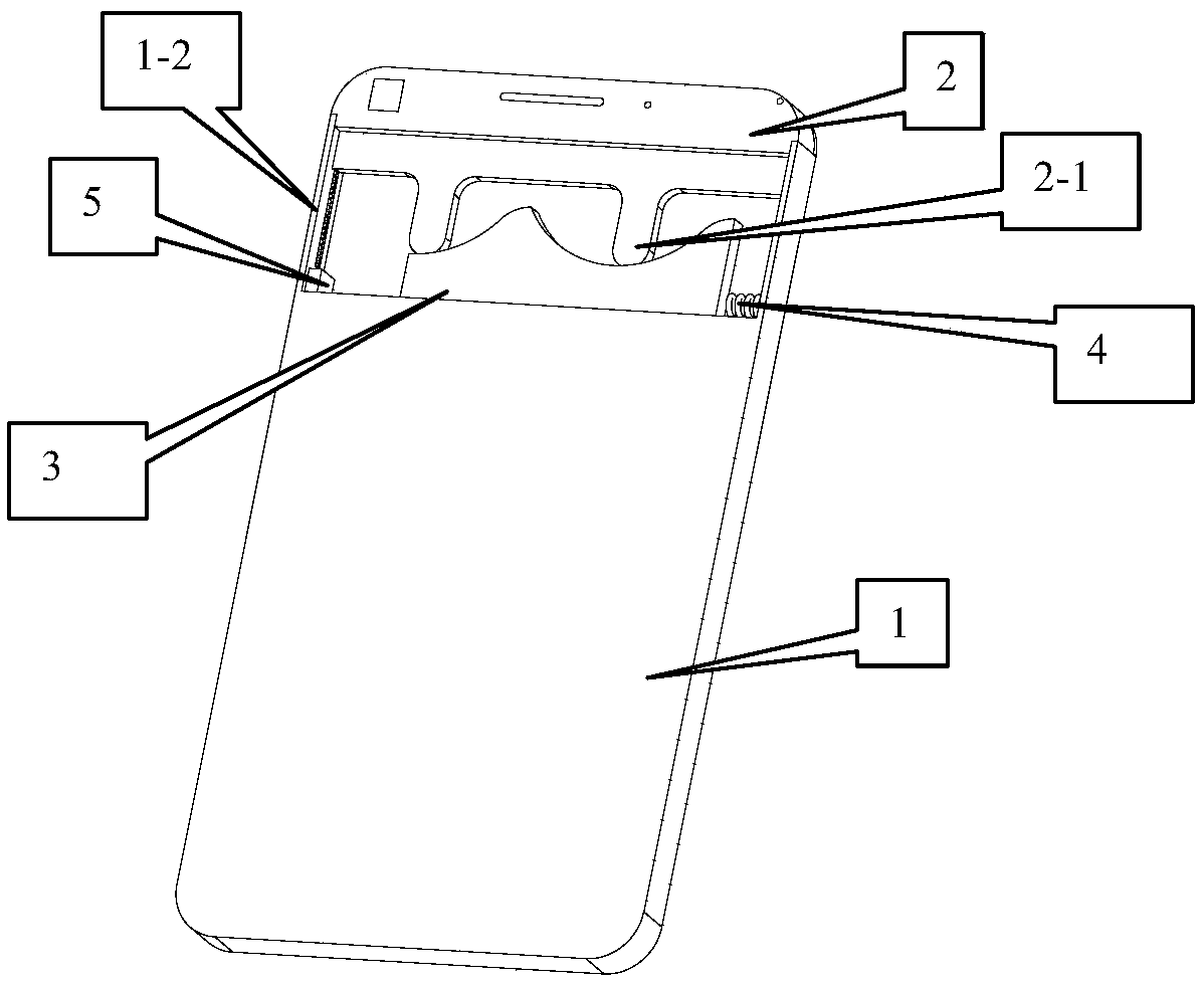
[0022] The first embodiment of the present invention provides a telescopic mechanism, the telescopic mechanism includes a telescopic part and an accommodating groove for accommodating the telescopic part, the telescopic part can protrude out of the accommodating groove, and can also be retracted Hidden in the accommodating groove; the accommodating groove is provided with a telescopic driving part that drives the telescopic part to extend or retract the accommodating groove; the telescopic driving part includes an electromagnet, The telescopic mechanism controls the extension or retraction of the telescopic part by controlling the energization or de-energization of the electromagnet. In the telescopic mechanism provided by the embodiment of the present invention, the telescopic power comes from the electromagnet, and the electromagnet occupies a small space, and is easy to control and low in cost.

[0023] It should be noted that, in the description of the embodiments of the p...

no. 2 example

[0044] On the basis of the first embodiment of the present invention, the second embodiment of the present invention proposes another telescoping mechanism. The realization of the telescopic mechanism of the second embodiment of the present invention is basically similar to that of the first embodiment of the present invention. The differences include : The moving direction of the telescopic guide block, which will be described in detail below.

[0045] Here, the telescopic driving part may include a first electromagnet, a telescopic guide block, and a first return spring; the telescopic guide block is slidably disposed at the bottom of the accommodating tank, and can move based on the bottom of the accommodating tank, Here, the moving direction of the telescopic guide block is neither parallel nor perpendicular to the telescopic movement direction.

[0046] The top of the telescopic guide block is provided with an ejection structure that can push the telescopic part to perfor...

no. 3 example

[0049] On the basis of the first embodiment of the present invention, the third embodiment of the present invention proposes yet another telescoping mechanism. The difference between the third embodiment of the present invention and the telescopic mechanism of the first embodiment of the present invention lies in the setting of the telescopic drive components method, which will be described in detail below.

[0050] The telescopic driving part includes at least two electromagnets, and the telescopic mechanism controls the extension or retraction of the telescopic part by controlling the energization or de-energization of the electromagnets.

[0051] As an implementation, the telescopic driving part includes a second electromagnet, a third electromagnet, and a telescopic guide block; the telescopic guide block is slidably arranged at the bottom of the accommodating tank, and can Make a movement that is not parallel to the direction of the telescopic movement; one end of the tel...


PUM


Abstract

The invention discloses a telescopic mechanism, a camera device and a terminal. The telescopic mechanism comprises a telescopic part and an accommodating groove for accommodating the telescopic part,wherein the telescopic part can extend out of the accommodating groove and can also retract to be hidden in the accommodating groove; a telescopic driving part for driving the telescopic part to do telescopic motion of extending out of or retracting into the accommodating groove is arranged in the accommodating groove; and the telescopic driving part comprises an electromagnet, and the telescopicmechanism controls the telescopic part to stretch out or draw back by controlling the electromagnet to be powered on or powered off.

Description

technical field [0001] The invention relates to the manufacturing technology of electronic equipment, in particular to a telescoping mechanism, a camera device and a terminal. Background technique [0002] With the advancement of technology and the improvement of living standards, users have higher and higher requirements for mobile phones. In order to obtain a larger screen while keeping the front area of ​​the mobile phone unchanged, "full screen" has become a development trend of mobile phones. [0003] However, in mobile phones with "full screen" design, the placement of the front camera or earpiece has become a difficult problem. The current mainstream solutions are "notch" notch screen, "U" shaped notch screen and "chin" screen. Set on the notch or the chin, the earpiece is set on the notch or adopts solid vibration conduction; among them, the "notch" notch screen and the "U" notch screen are not beautiful in appearance, while in the "with chin" screen, when the user ...

Claims


Application Information

Patent Timeline
Patent Type & Authority Applications(China)
IPC IPC(8): H04M1/02H04N5/225
CPCH04M1/0264H04M1/0235H04N23/57
Inventor 王彦彬张磊
Owner ZTE CORP
Why Eureka
Try Eureka