PTC heater and manufacturing method thereof

A heater and manufacturing method technology, applied in the direction of heating element materials, etc., can solve the problems of poor product consistency, low power, high failure rate, etc., and achieve the effects of simplifying installation and connection steps, reducing production costs, and increasing heating power

Inactive Publication Date: 2020-01-03
佛山市南海区鑫之诚电子制造厂
View PDF0 Cites 0 Cited by
  • Summary
  • Abstract
  • Description
  • Claims
  • Application Information

AI Technical Summary

Problems solved by technology

The PTC heating element with this structure has the following defects: the heat conduction effect is poor, the conduction power is relatively low, and it cannot meet the requirements for higher power heating
At the same time, most of the PTC heater structures in the prior art are composed of multiple independent structures such as stainless steel pressing sheets, base plates, mica insulating backing plates, PTC heating plates, and high-temperature insulating paper. The structures are fixed and connected by rivets to achieve tight pressure The PTC heating element under this structure has the problems of complex structure of parts and poor heat conduction effect. Not only is the process efficiency low, the curing process is troublesome, and the consistency of the product is poor, it is inevitable to cause unsatisfactory results due to human operation errors. Qualified occurrence and unqualified rate is also high

Method used


Image

  • PTC heater and manufacturing method thereof
  • PTC heater and manufacturing method thereof
  • PTC heater and manufacturing method thereof

Examples


Embodiment 1

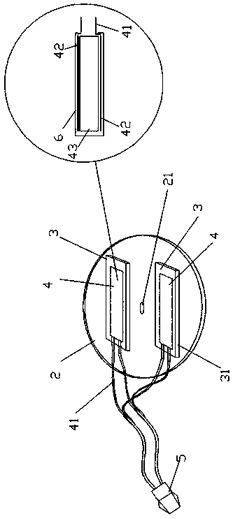
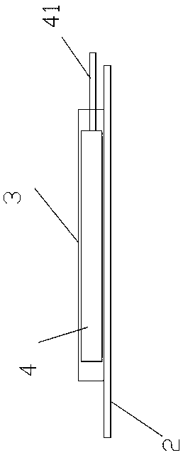
[0035] like figure 1 , 3 A PTC heater shown includes a heat-conducting aluminum plate 2 with a PTC heating unit 4 and a circular appearance shape. There is an aluminum-shaped card slot 3, which is equipped with a PTC heating unit 4. There are two aluminum-shaped card slots 3 to ensure uniform heating. The aluminum-shaped card slot 3 includes a cover plate 32 and a connecting cover plate 32. The clamping position 31 on the side, the clamping position 31 is located on the heat-conducting aluminum plate 2, forming a hollow structure transparent from front to back, and its size is adapted to the PTC heating unit 4. Described PTC heating unit 4 comprises PTC heating sheet 43, insulating paper 6 and electrode sheet 42, and described electrode sheet 42 is arranged on the upper and lower surface of PTC heating sheet 43 respectively, and the integral body of described electrode sheet 42 and described PTC heating sheet 43 wrapped in the insulating paper 6 . The aluminum-shaped card s...

Embodiment 2

[0048] Such as Figure 5 The structure of the clamping position 31 in the manufacturing method of the PTC heater described in this embodiment can also be inclined in the same direction as a whole, and the parallel inclination in the same direction can ensure the uniformity of the pressure on the whole. It will cause the aluminum groove to deform under the action of pressure.

Embodiment 3

[0050] Such as Image 6 The structure of the clamping position 31 in the manufacturing method of the PTC heater described on the basis of not changing other structures in this embodiment can also adopt the convex shape of the middle part to facilitate the pressing down of the aluminum-type card slot.


PUM


Abstract

The invention relates to the technical field of PTC heating and particularly relates to a PTC heater and a manufacturing method thereof. The PTC heater comprises a PTC heating unit and a heat conduction aluminum plate, wherein a heat conduction aluminum plate positioning hole is formed in the middle of the heat conduction aluminum plate; aluminum type clamping grooves are formed in the two sides of the positioning hole; the PTC heating unit is installed in the aluminum type clamping groove; and the aluminum type clamping grooves and the heat conduction aluminum plate are of an integrated structure formed by pulling out aluminum materials. The PTC heater and the manufacturing method thereof have the characteristics of fewer integrated processing consumables, simple structure, low productioncost, easiness in processing, high heat conduction efficiency and high heating power per unit volume.

Description

technical field [0001] The invention relates to the technical field of PTC heating, in particular to a PTC heater and a manufacturing method thereof. Background technique [0002] PTC heater is also called PTC heating element, which is composed of PTC ceramic heating element and aluminum tube. This type of PTC heater has the advantages of small thermal resistance and high heat exchange efficiency. It is an electric heater with automatic constant temperature and power saving. The outstanding feature lies in the safety performance. Under any application conditions, there will be no "redness" phenomenon on the surface of the electric heating tube heater, which will cause burns, fire and other safety hazards. It is widely used in disinfection cabinets, air conditioners, ovens and other industries. [0003] Most of the PTC heating elements are equipped with one or more PTC heating units in a metal shell. The PTC heating unit and the metal shell are not squeezed tightly, and ther...

Claims


Application Information

Patent Timeline
Patent Type & Authority Applications(China)
IPC IPC(8): H05B3/18
CPCH05B3/18
Inventor 叶立成
Owner 佛山市南海区鑫之诚电子制造厂
Why Eureka
Try Eureka