Eureka AIR delivers breakthrough ideas for toughest innovation challenges, trusted by R&D personnel around the world.

Rocker arm device

A technology for installing shafts and rotating shafts, which is applied in the direction of pivot connection, supporting machines, mechanical equipment, etc., which can solve the problems of inability to adjust, easy shaking of the rocker arm and maximum load bearing, etc., to achieve convenient operation, stable and reliable support force, and wide application range wide effect

Active Publication Date: 2020-01-07
SHENZHEN COMEN MEDICAL INSTR
View PDF5 Cites 4 Cited by
  • Summary
  • Abstract
  • Description
  • Claims
  • Application Information

AI Technical Summary

Problems solved by technology

[0005] The technical problem to be solved by the present invention is to provide a rocker device, aiming to solve the problem that the existing rocker arm is easy to shake after locking and the maximum load cannot be adjusted

Method used


Image

  • Rocker arm device
  • Rocker arm device
  • Rocker arm device

Examples


Embodiment Construction

[0048] In order to make the object, technical solution and advantages of the present invention more clear, the present invention will be further described in detail below in conjunction with the examples. It should be understood that the specific embodiments described here are only used to explain the present invention, not to limit the present invention.

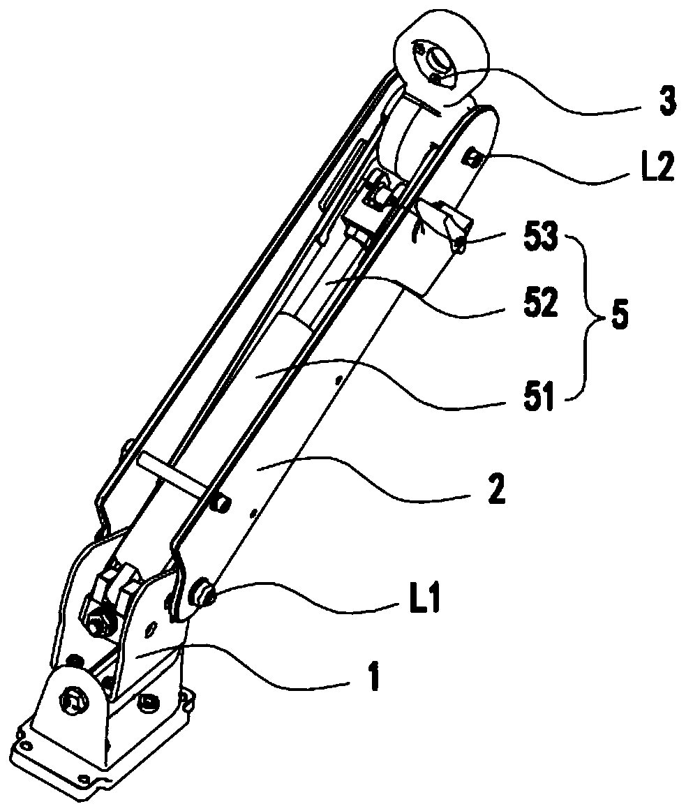
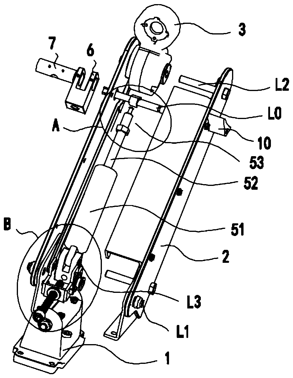
[0049] The invention provides a rocker device, the perspective view is as figure 2 As shown, the exploded diagram is as image 3 As shown, a partial view such as Figure 4 As shown, it includes a base 1, a rocker arm 2, a tray 3, a reciprocating assembly 4 and a gas spring 5. One end of the rocker arm 2 is hinged on the base through a first installation axis L1, and the other end is hinged on the base through a second installation axis L2. Hinged on the tray 3, the reciprocating assembly 4 is arranged on the side of the rocker arm 2 close to the tray 3 through the rotating shaft L0, and the rotating shaft L0 drives the r...


PUM


Abstract

The invention provides a rocker arm device which comprises a base, a rocker arm and a tray. One end of the rocker arm is hinged to the base through a first installation shaft, and the other end of therocker arm is hinged to the tray through a second installation shaft. The rocker arm device further comprises a reciprocating motion assembly and an air spring. The reciprocating motion assembly is arranged on the side, close to the tray, of the rocker arm through a rotating shaft and conducts reciprocating motion along with rotation of the rotating shaft. The air spring comprises a fixed part, atelescopic part and an ejector pin which are sequentially connected, the fixed part is hinged to the base through a third installation shaft, and the telescopic part supports the rocker arm. The reciprocating motion assembly acts on the ejector pin and is used for locking or unlocking the air spring. A third rotating shaft is located beyond the area which the rocker arm passes when the rocker armrotates to the extreme position, and the position of the third installation shaft is adjustable. Due to locking and unlocking operation of the rocker arm device, accurate control can be achieved by referring to the long distance end and the short distance end of the reciprocating motion assembly, operation is convenient, in addition, the supporting force of the air spring is stable and reliable,the bearing capability can be adjusted, and the application range is wider.

Description

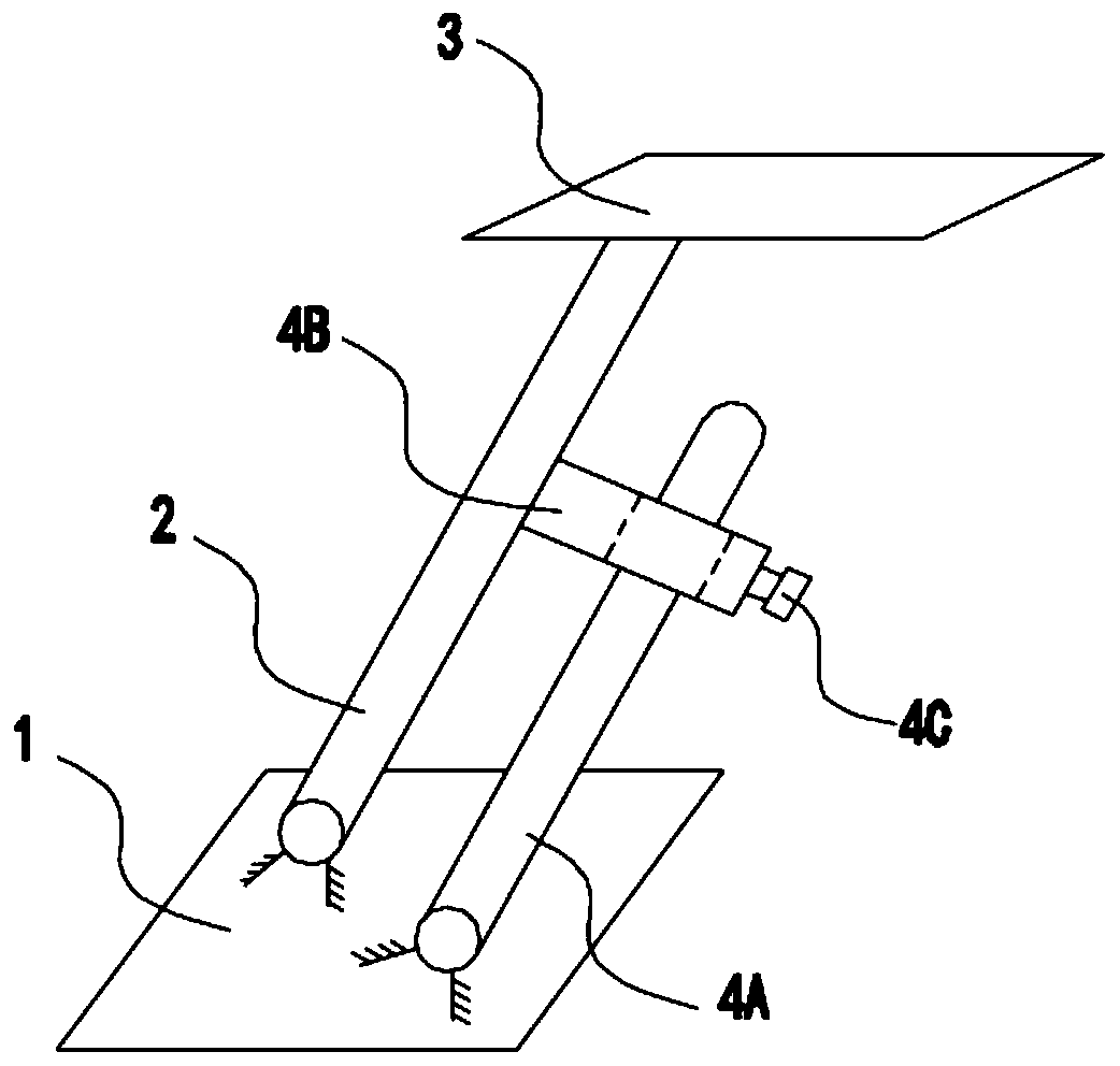
technical field [0001] The invention belongs to the technical field of mechanical installation, and in particular relates to a rocker arm device. Background technique [0002] Rocker devices, such as figure 1 As shown, it generally includes a base 1 , a rocker 2 , and a tray 3 hinged in turn. The base plays a fixed role, such as being fixed on a wall, and the tray is used to carry items such as TVs and monitors. Items can be adjusted to a suitable height by adjusting the rotation angle of the swing arm. The existing rocker arm adjustment structure includes an adjustment rod 4A, an adjustment sleeve 4B fixed on the rocker arm 2, and a locking bolt 4C. One end of the adjustment rod 4A is hinged on the base 1, and the other end is sleeved on the On the adjusting sleeve 4B, the locking bolt 4C is used to lock and fix the adjusting rod 4A and the adjusting sleeve 4B. [0003] When it is necessary to adjust the inclination angle of the rocker arm 2, loosen the lock bolt 4C, rot...

Claims


Application Information

Patent Timeline
IPC IPC(8): F16M11/06F16C11/04F16C11/10
CPCF16M11/06F16C11/04F16C11/10
Inventor 肖珊珊扈钧谢超群雷文斌
Owner SHENZHEN COMEN MEDICAL INSTR
Why Eureka
Eureka Blog
Learn More