Air gauge of electronic beam

A technology of pneumatic measuring instrument and column pneumatic quantity, which is applied in the direction of instruments, measuring devices, and utilizing fluid devices, etc., which can solve problems such as easy shaking, small contact area, and poor stability during use, so as to avoid shaking and improve stability sexual effect

Inactive Publication Date: 2020-01-07
CHONGQING KANGTIAN GEAR
View PDF9 Cites 0 Cited by
  • Summary
  • Abstract
  • Description
  • Claims
  • Application Information

AI Technical Summary

Problems solved by technology

[0003] When the existing electronic column type pneumatic measuring instrument is actually used, the contact area between the base and the placing surface after the pneumatic measuring instrument is placed is small, which makes the stability during placement not good, and it is easy to shake during use

Method used


Image

  • Air gauge of electronic beam
  • Air gauge of electronic beam
  • Air gauge of electronic beam

Examples


Embodiment approach

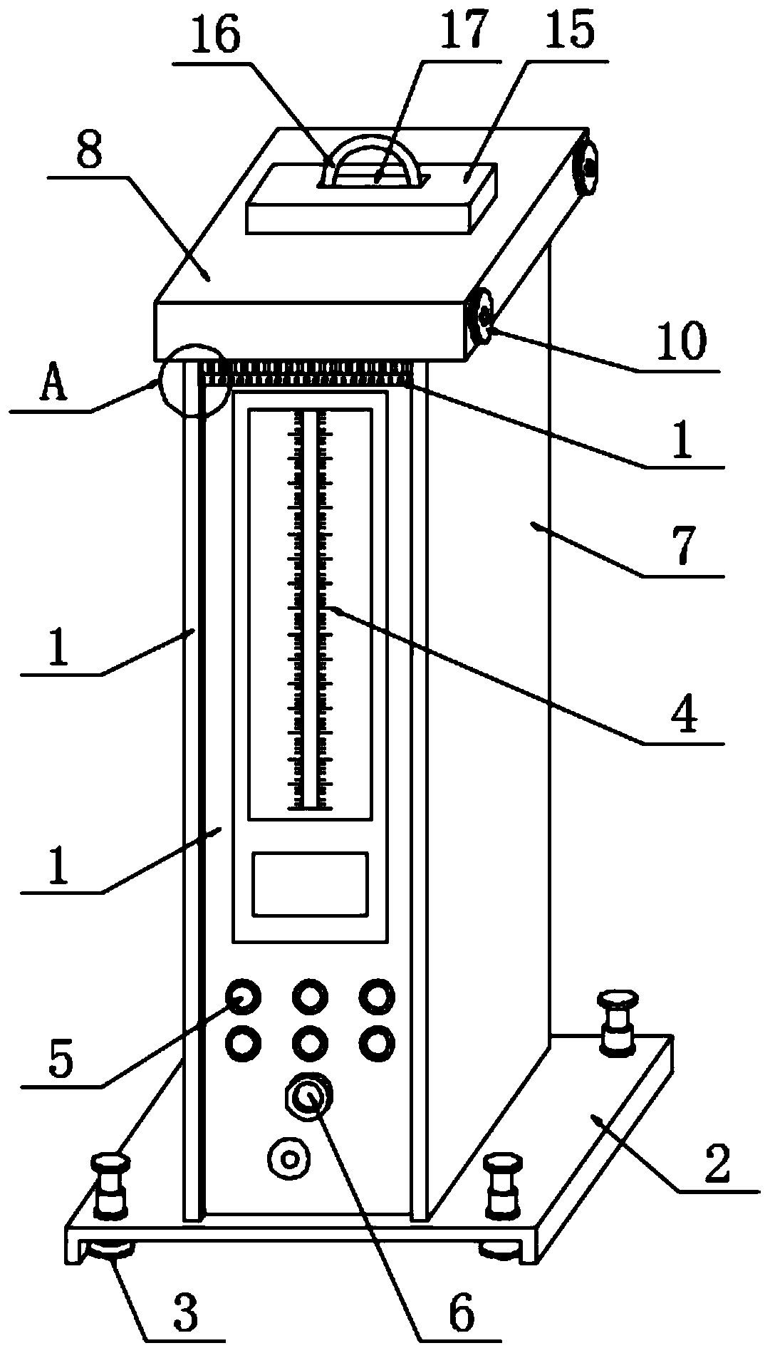
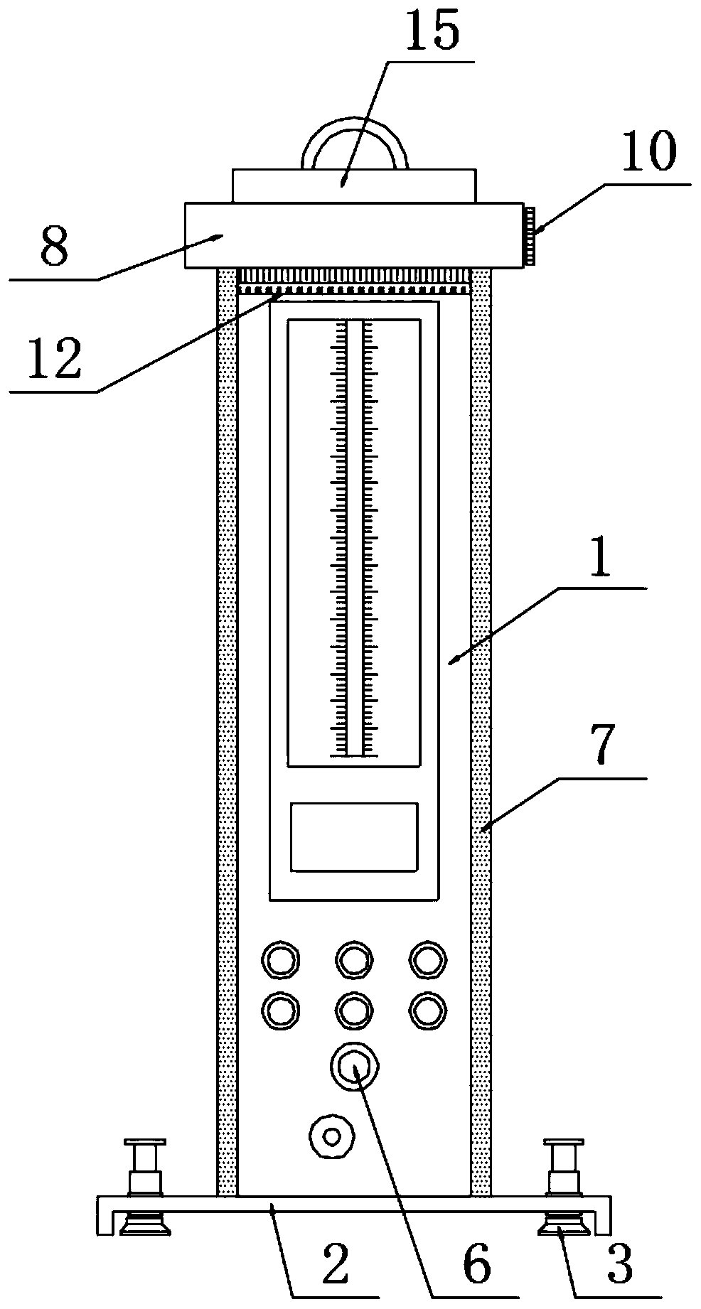
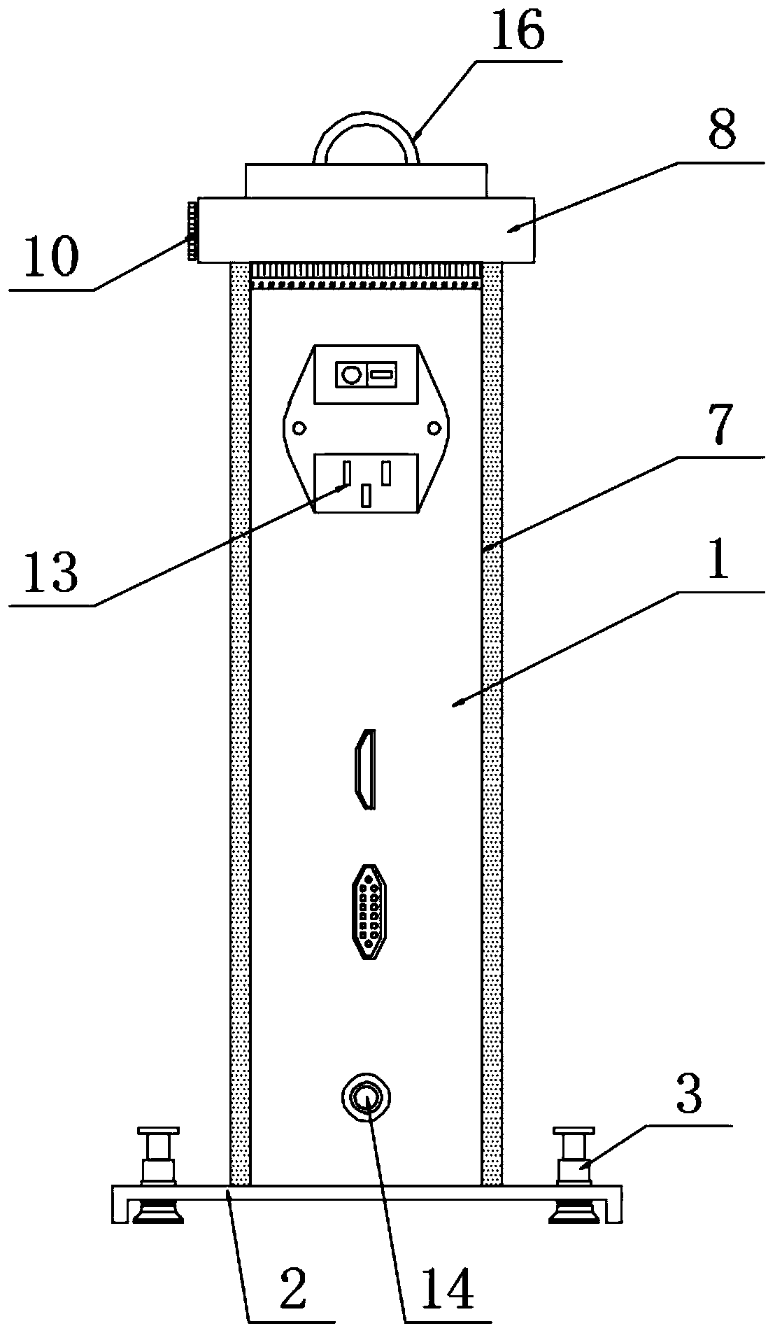
[0044] The specific implementation method is as follows: the protective plate 7 is connected to the two outer walls of the pneumatic measuring instrument body 1, the top of the protective plate 7 is connected to the protective shell 8, and the inside of the protective shell 8 is close to the front and rear sides of the pneumatic measuring instrument body 1 Both are connected with rotating shafts 9, and one end of the two rotating shafts 9 is located on the outside of the pneumatic measuring instrument body 1, and both are connected with knobs 10, and the outside of the rotating shafts 9 is located inside the protective case 8 and is wound with a dustproof cloth 11. The bottom end of each dustproof cloth 11 is located at the front and rear sides of the pneumatic measuring instrument body 1 and is connected with a counterweight rod 12, and the edge of the protective plate 7 corresponding to the end of the counterweight rod 12 is vertically provided with a limit chute 71, the bala...


PUM


Abstract

The invention discloses an air gauge of an electronic beam, and particularly relates to the field of air gauges. The air gauge comprises an air gauge body, wherein a base is arranged at the bottom ofthe air gauge body, absorption mechanisms are arranged at positions, near to four corners, of the interior of the base, a graduation marking line is arranged on a front surface of the air gauge body,a parameter setting button is arranged at a position, arranged below the graduation marking line, of the front surface of the air gauge body, a measurement head output connector is arranged below theparameter setting button, protection plates are connected with two outer side walls of the air gauge body, a socket is arranged at a rear surface of the air gauge body, an air inlet connector is arranged below the socket, and each absorption mechanism comprises a metal tube fixedly connected with an inner wall of the base. By the air gauge, the stability of the air gauge during placement is improved, swinging is prevented during the application process, and a dustproof effect of the air gauge can be prevented when the air gauge is not used.

Description

technical field [0001] The invention relates to the field of pneumatic measuring instruments, more specifically, the invention relates to an electronic column pneumatic measuring instrument. Background technique [0002] The measurement principle of the pneumatic measuring instrument is a comparative measurement method. The measurement method is to convert the length signal into an airflow signal, and pass the buoy indication value in the graduated glass tube, which is called a buoy-type pneumatic measuring instrument; or convert the gas signal through a gas-electric converter Converted to electrical signals, the light column indication value composed of luminescent tubes is called an electronic column pneumatic measuring instrument; a pneumatic measuring instrument is a measuring instrument that can be assembled with multiple sets, and it can be matched with different pneumatic measuring heads to achieve a variety of parameters. Due to its many advantages, the pneumatic mea...

Claims


Application Information

Patent Timeline
IPC IPC(8): G01B13/00G01B13/02
CPCG01B13/00G01B13/02
Inventor 刘怀山马健陶华兵刘彤王灼亮宋小波
Owner CHONGQING KANGTIAN GEAR
Why Eureka
Try Eureka