Sensor weighing device

A weighing device and sensor technology, applied in the direction of measuring device, detailed information of weighing equipment, instruments, etc., can solve the problem of easy deformation/deformation of weighing mechanical structure, improve weighing accuracy and use effect, and simplify the burden. force effect

Pending Publication Date: 2020-01-07
METTLER TOLEDO (CHANGZHOU) MEASUREMENT TECH CO LTD +2
View PDF0 Cites 0 Cited by
  • Summary
  • Abstract
  • Description
  • Claims
  • Application Information

AI Technical Summary

Problems solved by technology

[0007] The technical problem to be solved by the present invention is to provide a sensor weighing device in order to overcome the defect that the weighing mechanical structure is easily deformed / deformed in the prior art

Method used


Image

  • Sensor weighing device
  • Sensor weighing device
  • Sensor weighing device

Examples


Embodiment 1

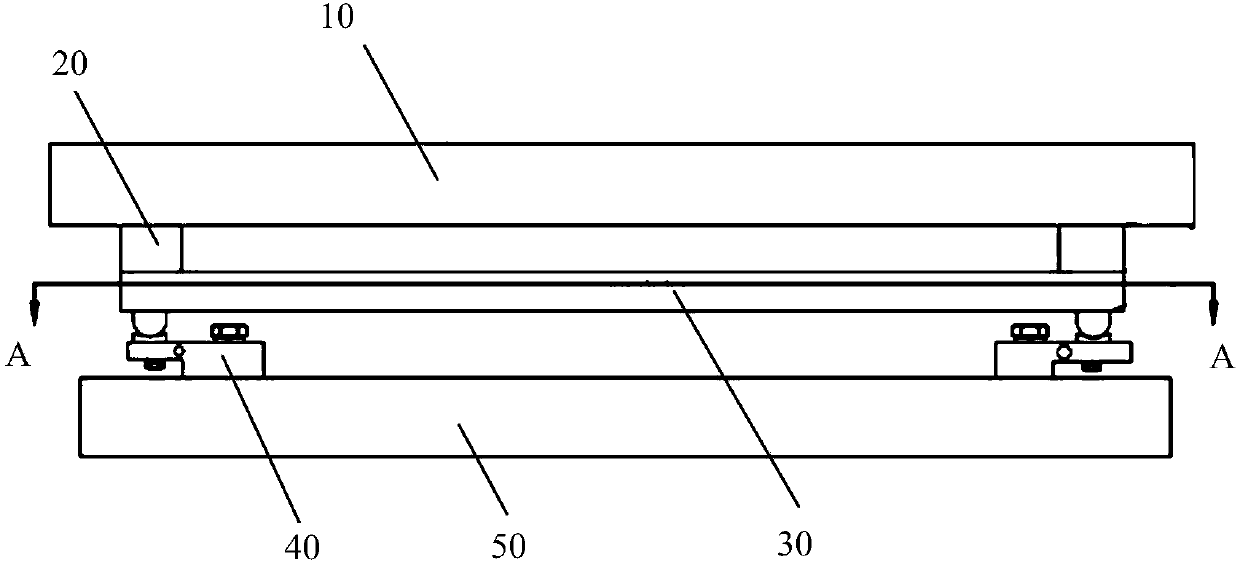
[0067]figure 1 It is a structural schematic diagram of Embodiment 1 of the sensor weighing device of the present invention. figure 2 for figure 1 A cross-sectional view taken along line A-A.

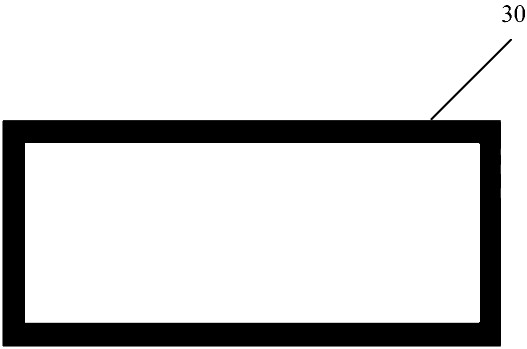
[0068] Such as figure 1 and figure 2 As shown, the present invention discloses a sensor weighing device, which specifically includes a weighing bearing part 10, a plurality of transition parts 20, a weighing isolation part 30, a plurality of weighing sensors 40 and a weighing support part 50, and weighs The bearing part 10 is mainly used to support the object to be weighed. The transition part 20 is arranged on the weighing isolation part 30 respectively, and the weighing bearing part 10 is arranged on the transition part 20, so that the transition part 20 connects the weighing bearing part 10 and the weighing isolation part 30, and the weighing bearing capacity is transferred to the The partition 30 is weighed. The load cell 40 is disposed at the bottom of the weighing isolation ...

Embodiment 2

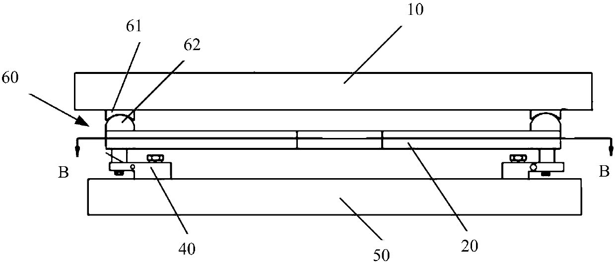
[0075] image 3 It is a structural schematic diagram of Embodiment 2 of the sensor weighing device of the present invention. Figure 4 for image 3 A cross-sectional view taken along line B-B.

[0076] Such as image 3 and Figure 4 As shown, the structure of this embodiment is basically the same as that of Embodiment 1, the difference is that the transition part adopts a movable mechanism 60, and the movable mechanism 60 includes an upper movable part 61 and a lower movable part 62, and the upper movable part 61 is fixedly connected to the bottom of the weighing bearing part 10 , and the lower movable part 62 is fixedly connected to the top of the weighing isolation part 30 .

[0077] At the same time, the lower end surface of the upper movable part 61 is set to a concave surface, and the upper end surface of the lower movable part 62 is set to a spherical surface, and the spherical surface matches the concave surface, and the upper movable part 61 and the lower movable p...

Embodiment 3

[0081] Figure 5 It is a structural schematic diagram of Embodiment 3 of the sensor weighing device of the present invention.

[0082] Such as Figure 5 As shown, the structure of the present embodiment is basically the same as that of the second embodiment, the difference is that the transition part adopts a movable mechanism 60, and the movable mechanism 60 includes an upper connecting part 63, a movable part 64 and a lower connecting part 65, The upper connecting part 63 is fixedly connected to the bottom of the weighing bearing part 10 , and the lower connecting part 65 is fixedly connected to the top of the weighing isolation part 30 . The movable part 64 is sandwiched between the upper connecting part 63 and the lower connecting part 65, and the movable part 64, the upper connecting part 63, and the lower connecting part 65 are in a rolling connection, forming the weighing bearing part 10 and the weighing isolation part 30 relative movement between them. The movable m...


PUM


Abstract

The invention provides a sensor weighing device, comprising a weighing bearing part, multiple transition parts and a weighing isolation part, multiple weighing sensors and a weighing supporting part,wherein the weighing bearing part is used for supporting a weighed object, the transition parts are respectively arranged on the weighing isolation part, the weighing bearing part is arranged on the transition parts, and the transition parts connect the weighing bearing part with the weighing isolation part; multiple weighing sensors are arranged at the bottom of the weighing isolation part; and the weighing supporting part is arranged at the bottom of the weighing sensors and used for supporting the weighing sensors. The sensor weighing device simplifies stresses of the weighing sensors, isolates deformation of a weighing structure and reduces influence of the deformation of the weighing structure on stress states of the weighing sensors, so that weighing accuracy and using effect of theweighing product are improved.

Description

technical field [0001] The invention relates to the field of weighing devices, in particular to a sensor weighing device. Background technique [0002] In the prior art, during the weighing application process of the multi-sensor weighing system, along with the change of the weighing load or the long-term use of the weighing mechanical structure, the weighing mechanical structure may undergo mechanical deformation / deformation. [0003] Due to the deformation / deformation of the weighing mechanical structure, the force state of the load cell of the weighing system will be different or changed relative to the force state of the load cell when the weighing system is calibrated, resulting in the introduction of A certain weighing influence / error will reduce the weighing application accuracy and effect of the weighing system. [0004] The existing weighing structure is usually divided into three layers: the bottom layer is the support layer, which is used to support and fix the l...

Claims


Application Information

Patent Timeline
Patent Type & Authority Applications(China)
IPC IPC(8): G01G23/00G01G21/02G01G21/28G01G21/23
CPCG01G23/005G01G21/02G01G21/28G01G21/23
Inventor 王沈辉陈登佑张凇孙沁
Owner METTLER TOLEDO (CHANGZHOU) MEASUREMENT TECH CO LTD
Why Eureka
Try Eureka