Novel developer supply container and developer supply method

A technology for supplying a container and a developer, which is applied in the direction of instruments, electrical recording processes using charge patterns, equipment using electrical recording processes using charge patterns, etc. Into the inner wall and outer wall, the developer is easy to fly in, etc., to achieve the effect of convenient pushing, reducing waste, and easy to push

Inactive Publication Date: 2020-01-07
JIANGXI KAILIDE TECH CO LTD
View PDF12 Cites 2 Cited by
  • Summary
  • Abstract
  • Description
  • Claims
  • Application Information

AI Technical Summary

Problems solved by technology

[0004] The purpose of the present invention is to provide a novel developer supply container and a developer supply method, to solve the above-mentioned background technology when we pour the developer into the developer replenishment container, due to the inner and outer walls of the developer replenishment container The structure causes part of the developer to easily fly into or float into the gap between the inner wall and the outer wall, resulting in the loss of developer, and at the same time affects the smoothness of the operation of the piston fitting on the developer replenishment container, and the snap ring of the developer replenishment container is installed At this time, because the clasp is not buckled, there is a certain risk that the clasp will return to its original shape, and there is a certain risk that the clasp will be pulled off. In this case, the piston on the refill container will shake and eventually loosen, resulting in Bad product

Method used


Image

  • Novel developer supply container and developer supply method
  • Novel developer supply container and developer supply method
  • Novel developer supply container and developer supply method

Examples


Embodiment Construction

[0029] The following will clearly and completely describe the technical solutions in the embodiments of the present invention with reference to the accompanying drawings in the embodiments of the present invention. Obviously, the described embodiments are only some, not all, embodiments of the present invention. The specific embodiments described here are only used to explain the present invention, not to limit the present invention. Based on the embodiments of the present invention, all other embodiments obtained by persons of ordinary skill in the art without making creative efforts belong to the protection scope of the present invention.

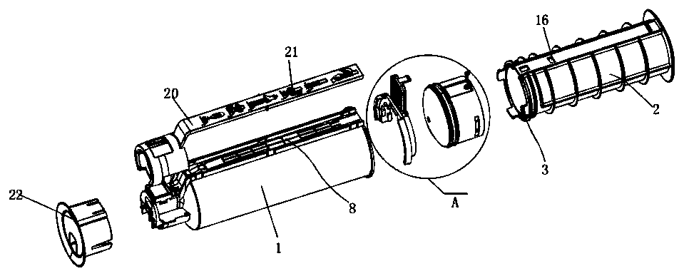
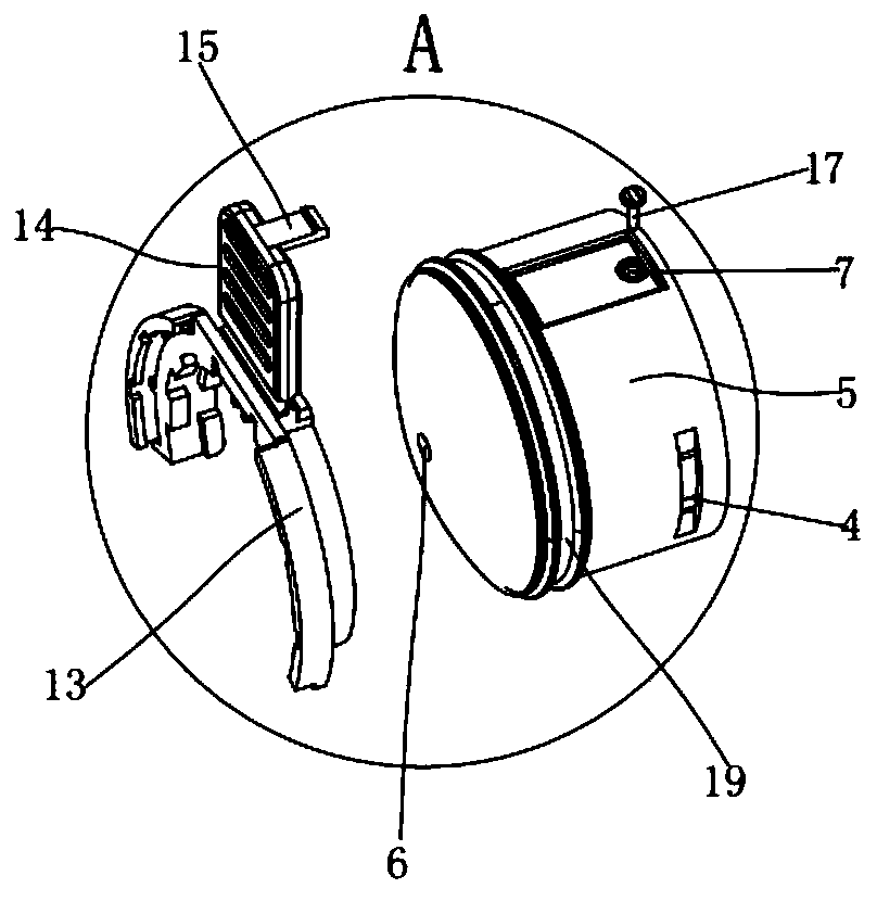
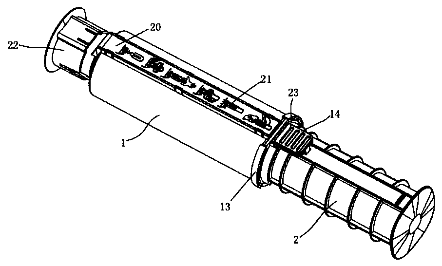
[0030] Such as figure 1 , figure 2 and Figure 4 As shown, the present invention provides a new type of developer supply container, which includes a container 1, a piston rod 2 and a piston sealing head 5, one end of the piston rod 2 is provided with a first chuck 3, and the first chuck 3 is clamped on the second In a clamping hole 4,...


PUM


Abstract

The invention discloses a novel developer supply container. The novel developer supply container comprises a container, a piston rod and a piston sealing head; a first clamping head is arranged at oneend of the piston rod; the first clamping head is clamped in a first clamping hole in the piston sealing head; the piston sealing head is inserted into the container; a first vent hole is formed in the piston sealing head; the first vent hole is communicated with a second vent hole; an insertion pin is fixedly connected to the outer side of one end of the piston rod; the insertion pin slides on the outer cylindrical surface of the container; a first conductive iron sheet is arranged at the end portion of the one end of the insertion pin; a second conductive iron sheet is arranged at the lowerside of the first conductive iron sheet; the end portions of the first conductive iron sheet and the second conductive iron sheet are electrically connected with a processor chip; the processor chipis fixed to the container; and one end, away from the piston rod, of the container is eccentrically provided with a powder outlet. With the novel developer supply container adopted, the waste of a developer is reduced; the smoothness of the piston sealing head in the container is improved; the piston sealing head can be conveniently inserted into the container; and the firmness of a clamping ringis improved. The novel developer supply container has the advantages of high safety and convenient use.

Description

technical field [0001] The invention belongs to the technical field of developer supply containers, and in particular relates to a new developer supply container. Meanwhile, the invention also provides a developer supply method. Background technique [0002] The developer refers to the agent that develops the latent image produced by the exposure of the photosensitive material into a visible image. From the perspective of chemical components, developers can be divided into two categories: inorganic compounds and organic compounds. The imaging of imaging equipment such as copiers and printers is inseparable from the developer. Generally, an electrophotographic type image forming apparatus such as an electrophotographic copier uses a developer of fine particles. In such an image forming apparatus, as the developer is consumed by the image forming operation, it is necessary to replenish the developer with a developer replenishing container. [0003] At present, when we pour ...

Claims


Application Information

Patent Timeline
Patent Type & Authority Applications(China)
IPC IPC(8): G03G15/08
CPCG03G15/0867G03G15/0877G03G15/0868G03G21/1647G03G2215/0675G03G2221/163
Inventor 祝金军李忠溪何家冰
Owner JIANGXI KAILIDE TECH CO LTD
Why Eureka
Try Eureka