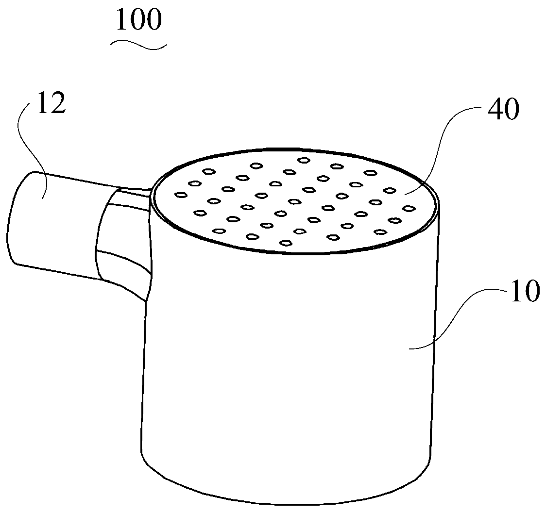
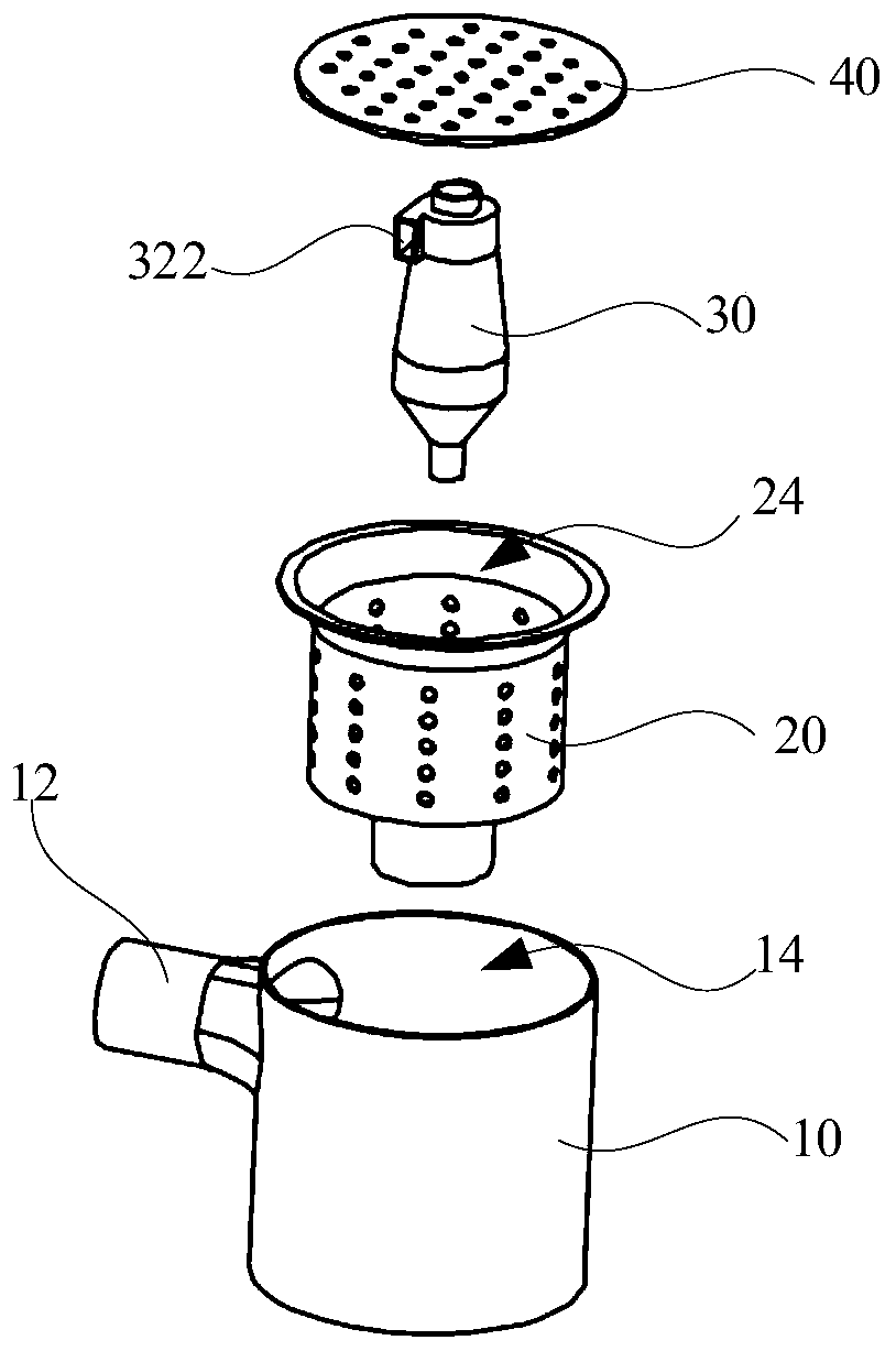
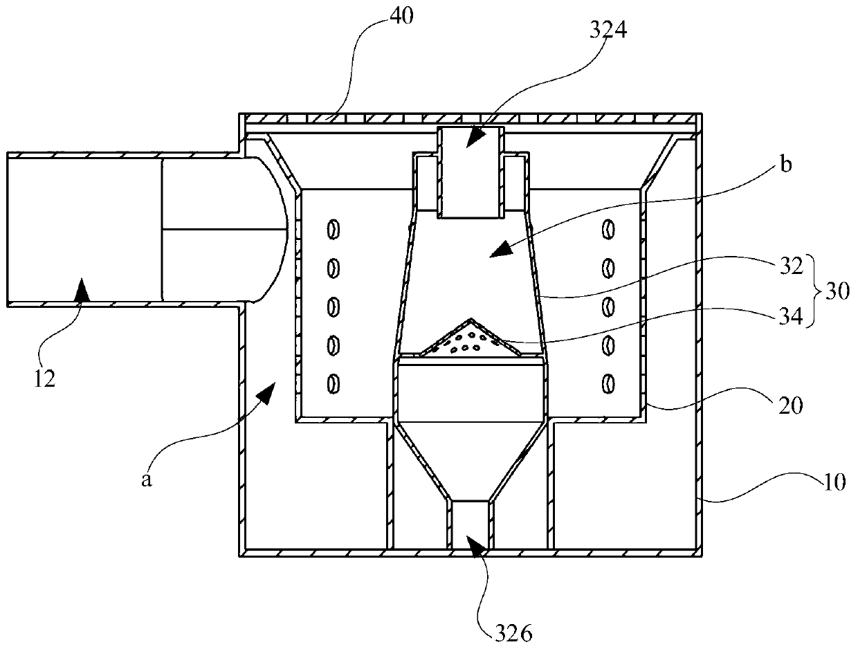
Dust collector, dust cup device and separating cone of dust cup device

A technology for separating cones and dust cups, which is applied to vacuum cleaners, suction filters, cleaning equipment, etc., can solve the problems of affecting the service life of motors, environmental pollution, and inability to separate dust and dirt, so as to improve the effect of air and dust separation and reduce the impact Effect

Pending Publication Date: 2020-01-10
GREE ELECTRIC APPLIANCES INC
View PDF0 Cites 2 Cited by
  • Summary
  • Abstract
  • Description
  • Claims
  • Application Information

AI Technical Summary

Problems solved by technology

[0004] Based on this, it is necessary to provide an improvement to the problem that the dust cup device in the prior art cannot separate part of the dust with a small particle size, which will be discharged with the airflow, affect the service life of the motor, and cause pollution to the environment. Vacuum cleaner, dust cup device and separating cone with the above-mentioned defects

Method used


Image

  • Dust collector, dust cup device and separating cone of dust cup device
  • Dust collector, dust cup device and separating cone of dust cup device
  • Dust collector, dust cup device and separating cone of dust cup device

Examples


Embodiment Construction

[0026] In order to facilitate understanding of the present invention, the present invention will be described more fully hereinafter with reference to the related drawings. Preferred embodiments of the invention are shown in the accompanying drawings. However, the present invention may be embodied in many different forms and is not limited to the embodiments described herein. Rather, these embodiments are provided so that a thorough and complete understanding of the present disclosure is provided.

[0027] It should be noted that when an element is referred to as being "fixed to" another element, it can be directly on the other element or intervening elements may also be present. When an element is referred to as being "connected" to another element, it can be directly connected to the other element or intervening elements may also be present. The terms "vertical," "horizontal," "left," "right," and similar expressions are used herein for illustrative purposes only.

[0028...


PUM


Abstract

The invention relates to a dust collector, a dust cup device and a separating cone of the dust cup device. The separating cone comprises a separating cone body and a reflecting screen, wherein the separating cone body is provided with an inner cavity, an air inlet, an air exhaust outlet and a dust collecting hole, the air inlet is positioned in the peripheral side wall of the top end of the separating cone body, the air exhaust outlet is positioned at the axial top end of the separating cone body, and the dust collecting hole is positioned at the axial bottom end of the separating cone body; the reflecting screen is matched in the inner cavity; and a gap is formed between the reflecting screen and the peripheral side wall of the inner cavity, and the reflecting screen is provided with a plurality of air flow holes. In downward air flow, dust-containing air flow close to the peripheral side wall of the inner cavity moves downwards through the gap between the reflecting screen and the peripheral side wall of the inner cavity; meanwhile, in the air flow moving downwards, dust-free air flow close to the middle of the inner cavity moves upwards through the reflecting of the reflecting screen, and further is exhausted from the air exhaust outlet, then the air flow continuing moving downwards is not influenced, therefore, the phenomenon that the dust in the air flow downwards moving is brought out of the air exhaust outlet by the air flow moving upwards is avoided, thus the air-dust separating effect is improved, and the influences on the service life of a motor and the environment are reduced.

Description

technical field [0001] The invention relates to the technical field of dust collection equipment, in particular to a dust collector, a dust cup device and a separation cone thereof. Background technique [0002] With the continuous improvement of people's living standards, the requirements for living sanitation and environmental sanitation are also getting higher and higher. Vacuum cleaners have gradually become an indispensable household appliance in life. [0003] Generally, a vacuum cleaner has a dust cup device that filters and separates gas and dust in multiple layers. The gas and dust entering the dust cup device are separated by a cyclone, and the dust and dirt are collected in a dust collecting chamber, and the gas is discharged. However, in the dust cup device in the prior art, some dusts with small particle size cannot be separated, and they will be discharged with the airflow, affecting the service life of the motor and causing pollution to the environment. SUM...

Claims


Application Information

Patent Timeline
Patent Type & Authority Applications(China)
IPC IPC(8): A47L9/16
CPCA47L9/16A47L9/165A47L9/1666A47L9/1683
Inventor 任敏李锦坤李吉王德旭黄月林陈闪毅
Owner GREE ELECTRIC APPLIANCES INC
Why Eureka
Try Eureka