
Copper pipe bending machine

A technology of pipe bending machine and copper pipe, which is applied in metal processing equipment, feeding device, positioning device and other directions, can solve the problems such as the safety of operators cannot be guaranteed, the pipe bending machine cannot stand stably, and the bending of pipes is inaccurate, etc. Achieve the effect of reducing labor intensity, wide applicability, and accurate bending

Active Publication Date: 2020-01-10
安徽省荣源智能科技有限公司
View PDF5 Cites 3 Cited by
  • Summary
  • Abstract
  • Description
  • Claims
  • Application Information

AI Technical Summary

Problems solved by technology

[0005] The object of the present invention is to provide a copper pipe bending machine to solve the problem that the existing small pipe bending machine proposed in the above background technology cannot well fix the pipe to be bent in the groove inside the bending die, resulting in During the bending process of the pipe, the pipe will move, resulting in inaccurate bending of the pipe, and it is more likely that the pipe will fly out and cause an accident. , so that the pipe bender cannot stand stably during the working process, so that the safety of the operator cannot be guaranteed when bending the pipe

Method used


Image

  • Copper pipe bending machine
  • Copper pipe bending machine
  • Copper pipe bending machine

Examples


Embodiment Construction

[0024] The following will clearly and completely describe the technical solutions in the embodiments of the present invention with reference to the accompanying drawings in the embodiments of the present invention. Obviously, the described embodiments are only some, not all, embodiments of the present invention. Based on the embodiments of the present invention, all other embodiments obtained by persons of ordinary skill in the art without creative efforts fall within the protection scope of the present invention.

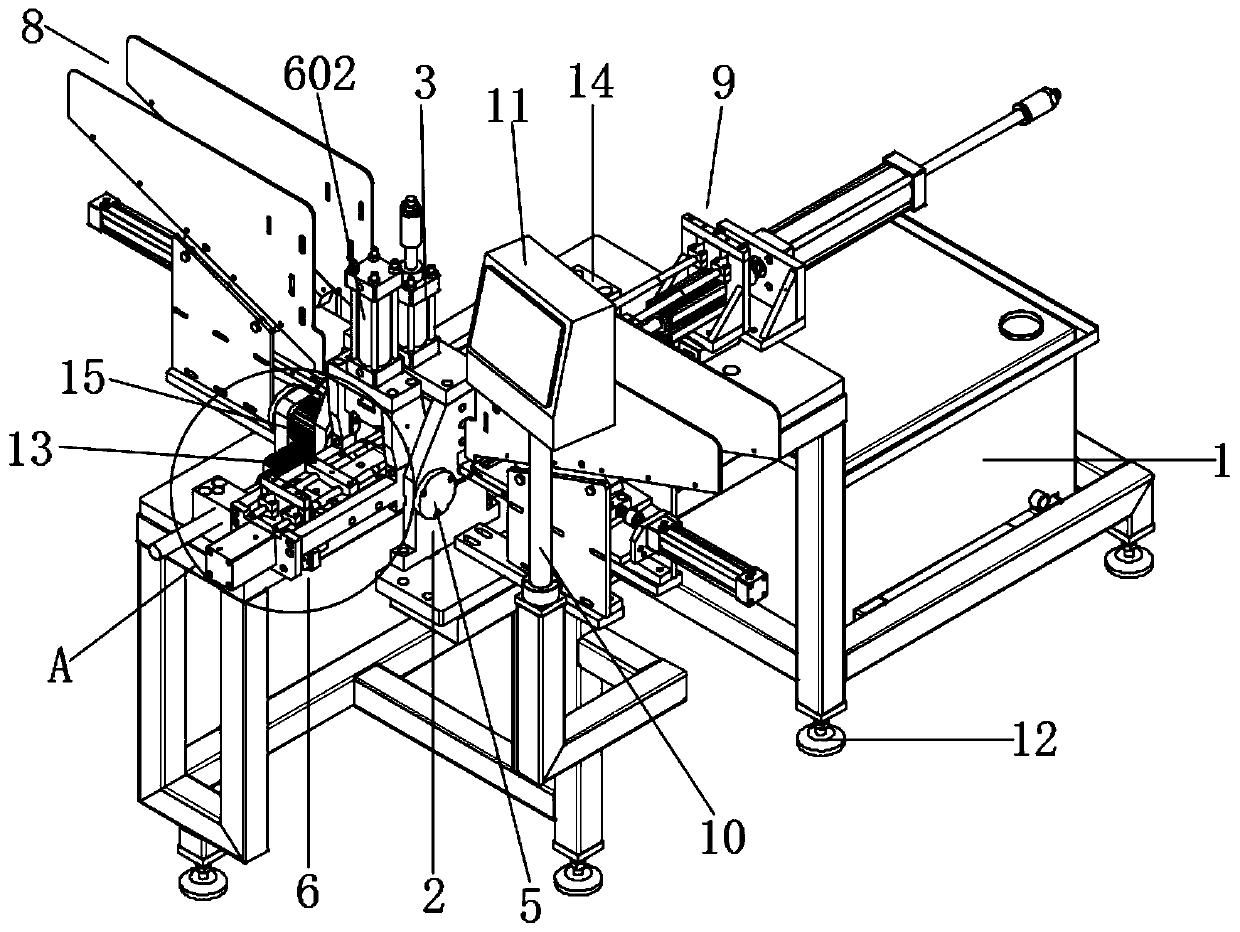
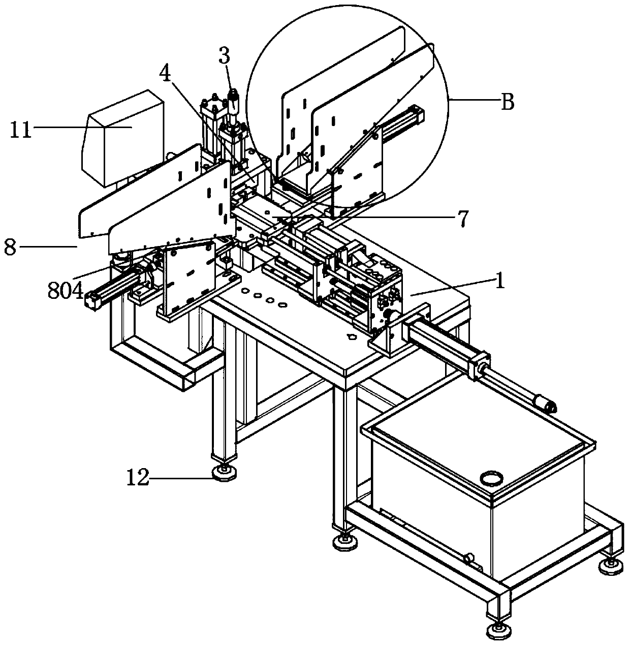
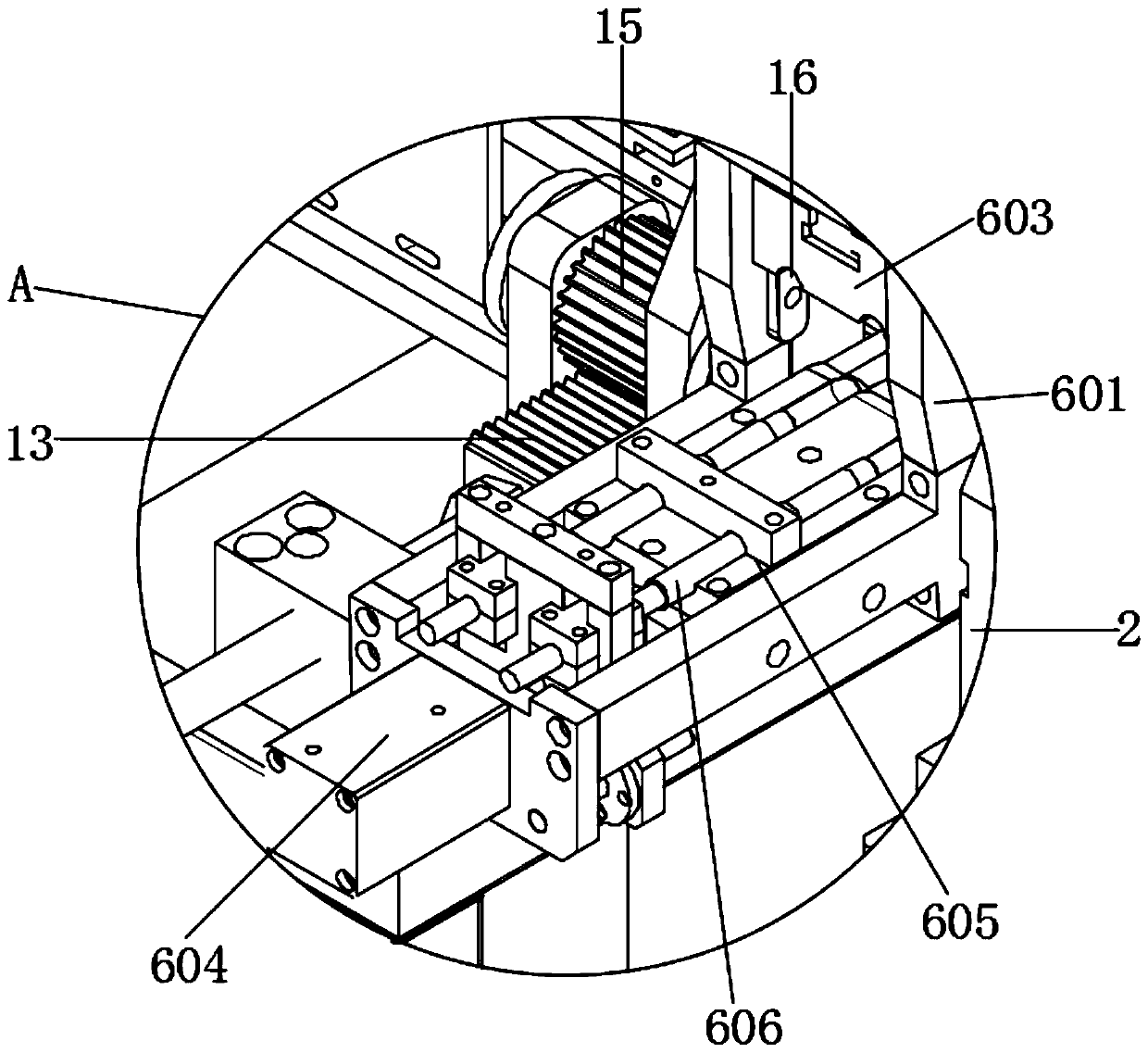
[0025] see Figure 1-5 , the present invention provides a technical solution: a copper pipe bending machine, including a frame 1, the upper end of the frame 1 is fixedly connected with a mold processing part 2, and the upper end of the mold processing part 2 is fixedly connected with an adjustable cylinder 3, so The power end of the adjustable cylinder 3 runs through the upper end of the mold processing part 2 and is fixedly connected to the follow-up mold 4. One s...


PUM


Abstract

The invention discloses a copper pipe bending machine in the technical field of pipe bending machines. The copper pipe bending machine comprises a rack. The upper end of the rack is fixedly connectedwith a mold processing piece. The upper end of the mold processing piece is fixedly connected with an adjustable air cylinder. The power end of the adjustable air cylinder penetrates through the upperend of a mold processing piece and is fixedly connected to a follow-up mold. One side of the mold processing piece is rotatably connected with a pipe bending mechanism through a rotating shaft. The upper end of the rack is fixedly connected with a placing plate on the other side of the mold processing piece. Feeding mechanisms are arranged at the front end and the rear end of the placing plate. Apositioning mechanism is arranged on the other side of the placing plate and at the upper end of the rack, so that a pipe needing to be bent can be firmly fixed in the placing plate and does not movein the bending process. Therefore, it is ensured that the pipe bending degree is accurate, and accidents caused after the pipe flies out are further avoided. The bending position of a short pipe canbe adjusted according to the positions of two sets of positioning plates. Pipe bending automation of the liquid storage device type short pipes is achieved. The working efficiency is greatly improved.The labor intensity of workers is reduced.

Description

technical field [0001] The invention relates to the technical field of pipe benders, in particular to a copper pipe bender. Background technique [0002] Pipe benders are roughly divided into CNC pipe benders, hydraulic pipe benders, etc., which are used in pipeline laying and repair in power construction, highway and railway construction, bridges, ships, etc., classified according to power types: hydraulic pipe benders, electric platform pipe benders Machine, pneumatic pipe bender, manual pipe bender, etc., classified according to the control method: CNC pipe bender, semi-automatic pipe bender, fully automatic pipe bender, etc., classified according to the type of work: single-head pipe bender, double-head pipe bender Machine, multi-head pipe bender, etc. The pipe bender is mainly used for bending steel pipes such as electric power construction, boilers, bridges, ships, furniture, decoration, etc. It has the advantages of multiple functions, reasonable structure, and simple...

Claims


Application Information

Patent Timeline
Patent Type & Authority Applications(China)
IPC IPC(8): B21D7/06B21D43/00
CPCB21D7/06B21D43/003
Inventor 叶紫淳
Owner 安徽省荣源智能科技有限公司
Learn More