A financial note folder
A bill clip and financial technology, applied in the field of financial bill clips, can solve the problems of thick stacking structure, reduced security, and large storage space.
- Summary
- Abstract
- Description
- Claims
- Application Information
AI Technical Summary
Problems solved by technology
Method used
Image
Examples
Embodiment 1
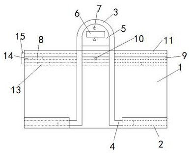
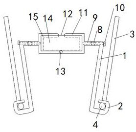
[0022] A financial paper folder, see figure 1 , The financial document holder includes a holder body, the holder body includes two oppositely arranged inverted "L"-shaped splints 1, the bending angles of the splints 1 are located on the outer side, see figure 2 , The angle between the longitudinal part of the splint 1 and the transverse part of the splint 1 is less than 90°; the lower end of the longitudinal part of the splint 1 is respectively provided with two outer flanging structures, the flanging structures are folded outward to form Flanging tube 2, an inverted "U"-shaped pressing rod 3 is arranged between the two folding tubes 2 respectively, and the lower end of the pressing rod 3 is respectively provided with a rotating rod 4 located in the folding tube 2 in an inverted "U" shape The upper end of the pressure rod 3 is respectively provided with a pressure plate 5 in the upper bending structure, the pressure plate 5 is provided with a hanging hole 6 and at least two hang...
Embodiment 2
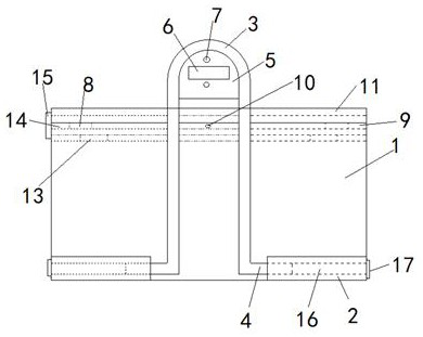
[0036] A financial receipt folder, similar to Example 1, except that, see image 3 , The rotating rod 4 is configured as a metal rod extending into the inner end of the flange tube 2, and a lower magnetic rod 16 is provided in the outer end of the flange tube 2. In this way, by increasing the number of hanging holes 6, the lower magnetic rod 16 can be extended into the hanging holes 6 to more stably hang the clamped financial documents.
[0037] Preferably, see Figure 4 , The outer end of the lower magnetic rod 16 is respectively provided with a lower magnetic baffle 17 located outside the flange tube 2. In this way, the lower magnetic baffle 17 can facilitate the taking operation of the lower magnetic rod 16 while avoiding all the lower magnetic rod 16 from extending into the flange tube 2. In addition, the end of the lower magnetic rod 16 and the end of the rotating rod 4 can be sucked and connected in the flange tube 2, so that the firmness and stability of the structure of ...
PUM
 Abstract
Description
Claims
Application Information
 - R&D
- Intellectual Property
- Life Sciences
- Materials
- Tech Scout
- Unparalleled Data Quality
- Higher Quality Content
- 60% Fewer Hallucinations
Browse by: Latest US Patents, China's latest patents, Technical Efficacy Thesaurus, Application Domain, Technology Topic, Popular Technical Reports.
© 2025 PatSnap. All rights reserved.Legal|Privacy policy|Modern Slavery Act Transparency Statement|Sitemap|About US| Contact US: help@patsnap.com


