
Engine oil tank oil supply system

A technology of oil supply system and engine, which is applied in the direction of engine components, machine/engine, charging system, etc., and can solve the problem of not being able to absorb oil

Pending Publication Date: 2020-01-10
SHENZHEN SAIMAI TECH CO LTD
View PDF0 Cites 0 Cited by
  • Summary
  • Abstract
  • Description
  • Claims
  • Application Information

AI Technical Summary

Problems solved by technology

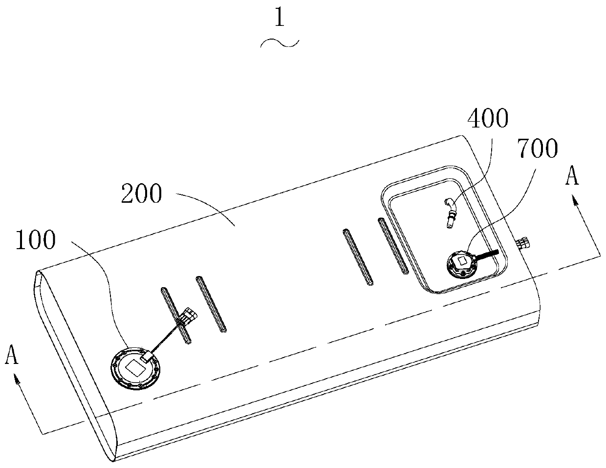
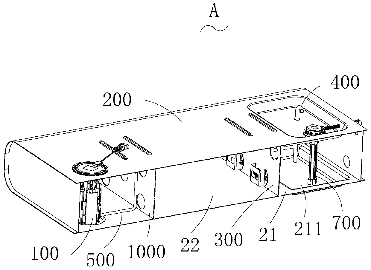
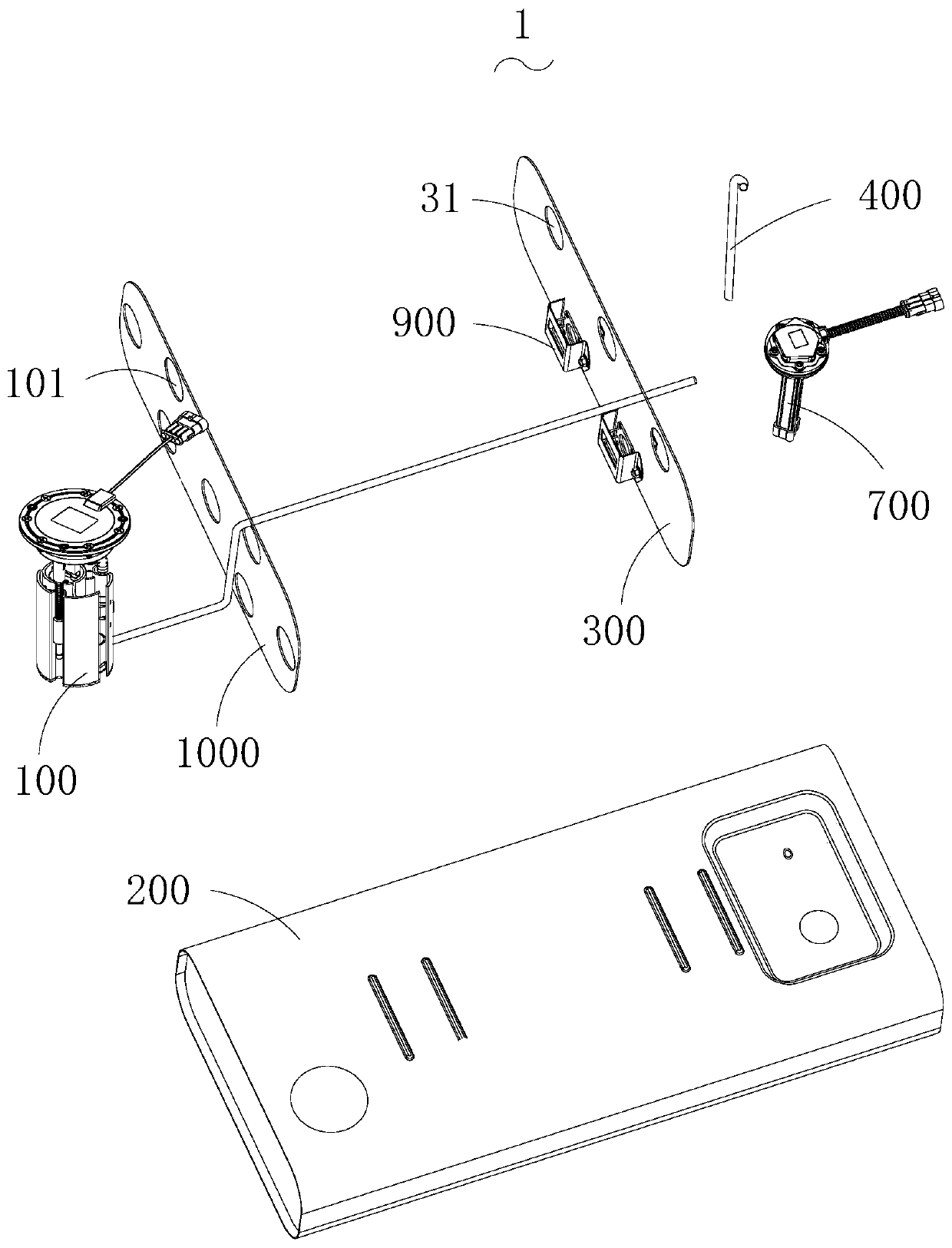
[0007] The first object of the present invention is to provide an engine oil tank oil supply system, which aims to solve the problem that the existing engine cannot absorb oil when the fuel tank of a fuel-fueled motor vehicle is relatively flat, when it is used on a slope or on a slope question

Method used


Image

  • Engine oil tank oil supply system
  • Engine oil tank oil supply system
  • Engine oil tank oil supply system

Examples


Embodiment Construction

[0053] The following will clearly and completely describe the technical solutions in the embodiments of the present invention with reference to the accompanying drawings in the embodiments of the present invention. Obviously, the described embodiments are only part of the embodiments of the present invention, not all of them. Based on the embodiments of the present invention, all other embodiments obtained by persons of ordinary skill in the art without creative efforts fall within the protection scope of the present invention.

[0054] It should be noted that all directional indications (such as up, down, left, right, front, back...) in the embodiments of the present invention are only used to explain the relationship between the components in a certain posture (as shown in the accompanying drawings). Relative positional relationship, movement conditions, etc., if the specific posture changes, the directional indication will also change accordingly.

[0055] It should also be...


PUM


Abstract

The invention discloses an engine oil tank oil supply system which comprises an oil tank with a cavity, a semi-sealing partition board, an oil suction pipe, a pump body component and an oil conveyingpipe, wherein the semi-sealing partition board is arranged in the oil tank to divide the cavity into a first oil tank and a second oil tank; the first oil tank and the second oil tank communicate witheach other; one end of the oil suction pipe is arranged in the first oil tank; the other end of the oil suction pipe is used for being connected with an engine; the pump body component is mounted onthe oil tank and is used for conveying the oil in the second oil tank to the first oil tank; one end of the oil conveying pipe is connected with the pump body component; and the other end of the oil conveying pipe is arranged in the first oil tank. The pump body component conveys oil in the second oil tank to the first oil tank to ensure that the oil level in the first oil tank is kept at certainheight, so that when a fuel oil motor vehicle must use a lower flat oil tank due to limitation of the entire vehicle arrangement, the engine can absorb oil under any road condition, especially when less fuel oil is left in the oil tank, the normal driving requirement of the fuel oil motor vehicle still can be met.

Description

technical field [0001] The invention relates to the technical field of engines, in particular to an oil supply system for an engine oil tank. Background technique [0002] Due to the limitations of the overall layout of the vehicle chassis, the fuel tank assembly is long and flat, so that when the vehicle is going uphill, downhill or standing on a slope, the engine will not be able to absorb fuel, and the fuel supply of the engine will be interrupted and cause failure. Flame failure. [0003] Under normal circumstances, the fuel of a vehicle equipped with an engine is mainly sucked into the engine from the inside of the fuel tank by the oil pump on the engine body using the effect of atmospheric pressure. The oil suction pipe of conventional automobile fuel tank is installed on the top of the fuel tank, and there is a pipe from the top to the bottom of the fuel tank. The bottom surface of the fuel tank, under certain conditions, the above-mentioned existing structure canno...

Claims


Application Information

Patent Timeline
Patent Type & Authority Applications(China)
IPC IPC(8): F02M37/00F02M37/04F02M37/44B60K15/03
CPCF02M37/0094F02M37/04F02M37/44F02M37/0076B60K15/03B60K2015/03223B60K2015/03236B60K2015/03243B60K2015/0344
Inventor 万楚华
Owner SHENZHEN SAIMAI TECH CO LTD
Learn More