A microstrip circulator, isolator and t/r component

A technology of circulators and microstrips, which is applied to waveguide devices, electrical components, circuits, etc., can solve the problems of large expansion coefficient gap, cracking of circulator magnets, uneven force, etc., and achieve the improvement of electrical performance indicators. Optimize the magnetic circuit and realize the effect of miniaturization

Active Publication Date: 2021-06-25
CHENGDU 899 SCI & TECH +1
View PDF9 Cites 0 Cited by
  • Summary
  • Abstract
  • Description
  • Claims
  • Application Information

AI Technical Summary

Problems solved by technology

[0003] At present, traditional circulators usually use manual soldering or gold wire bonding to electrically connect the pins to the circuit on the PCB, which is not only inefficient, but also unable to meet the requirements of high integration.
Although the structural design of existing circulators adopts surface mount technology (SMT: Surface Mount Technology), in fact, circulators are subjected to strong external forces and strong temperature shocks such as assembly, reflow soldering, and high-frequency energy transmission. , once the force on the gyromagnetic body of the circulator is uneven or the expansion coefficient of the PCB board is very different, it is very likely to cause the gyromagnetic body in the circulator to break

Method used


Image

  • A microstrip circulator, isolator and t/r component
  • A microstrip circulator, isolator and t/r component
  • A microstrip circulator, isolator and t/r component

Examples


Embodiment Construction

[0032] Embodiments of the present invention are described below through specific examples, and those skilled in the art can easily understand other advantages and effects of the present invention from the content disclosed in this specification. The present invention can also be implemented or applied through other different specific implementation modes, and various modifications or changes can be made to the details in this specification based on different viewpoints and applications without departing from the spirit of the present invention.

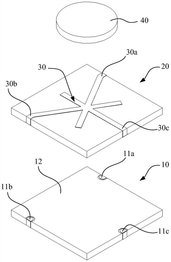
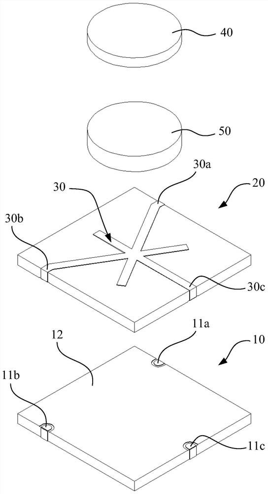
[0033] like figure 1 and figure 2 As shown, the microstrip circulator of the present invention includes a gyromagnetic layer 20 , a central conductor 30 disposed on the upper surface of the gyromagnetic layer 20 and a permanent magnet 40 disposed above the central conductor 30 . Meanwhile, the substrate 10 is also included.

[0034] The upper surface of the substrate 10 is provided with the first ground metal layer 12, the first si...


PUM


Abstract

The invention discloses a microstrip circulator, which can be applied to isolators and microwave communications, especially in T / R components. The microstrip circulator adds a substrate, and the upper surface of the substrate is provided with The first ground metal layer and a plurality of signal terminals, the lower surface of the substrate is provided with a plurality of welding areas that are electrically connected to the first ground metal layer and each signal terminal respectively; and the central conductor of the microstrip circulator The plurality of connection parts of the gyromagnetic layer respectively correspond to the plurality of connection ends provided on the lower surface of the gyromagnetic layer and are electrically connected; the gyromagnetic layer is arranged on the substrate, so that the lower surface of the gyromagnetic layer is connected to the upper surface of the substrate They are disposed face to face, and at the same time, the first ground metal layer is electrically connected to the second ground metal layer, and the connection terminals correspond to the signal terminals one by one and are electrically connected. Therefore, the present invention can not only achieve surface mounting with an external circuit through the substrate, but also reduce the impact of external force on the gyromagnet through the substrate.

Description

technical field [0001] The invention belongs to the technical field of circulator design and manufacture, and in particular relates to a microstrip circulator, an isolator and a T / R assembly using the microstrip circulator. Background technique [0002] The circulator is a non-reciprocal device with several terminals, which includes a gyromagnetic material made of gyromagnetic material. Due to the combined action of an external microwave magnetic field and a constant DC magnetic field, the gyromagnetic material produces gyromagnetic properties, so that the gyromagnetic material propagating in the gyromagnetic Electromagnetic waves are polarized and rotated to achieve one-way transmission of high-frequency signal energy, and are widely used in the field of microwave communications. With the development of communication technology, the requirements for circulators are getting higher and higher, for example, the circulators are required to be small in size, simple in process, a...

Claims


Application Information

Patent Timeline
Patent Type & Authority Patents(China)
IPC IPC(8): H01P1/387H01P1/36
CPCH01P1/36H01P1/387
Inventor 张如谭斯克何晨阳满吉令梁超
Owner CHENGDU 899 SCI & TECH
Why Eureka
Try Eureka