
Electric power connecting plug

A technology of power connection and plug, which is applied in the direction of connection, two-part connection device, parts of the connection device, etc. It can solve the problem of not clearly explaining the connection relationship between the positioning clip and the plug, the inconvenience of fixing and disassembling, and the installation of the positioning clip is not introduced. and other problems, to achieve the effect of simple fixing operation, firm fixing, and easy disassembly and assembly operation

Active Publication Date: 2020-01-10
日照润林电器有限公司
View PDF5 Cites 2 Cited by
  • Summary
  • Abstract
  • Description
  • Claims
  • Application Information

AI Technical Summary

Problems solved by technology

[0005] However, the patent document does not introduce how to install the positioning clip, and it does not clearly explain the connection relationship between the positioning clip plugs. If it is a fixed connection, this solution cannot be realized. If it is a sliding connection, at least one is required. The positioning clip can slide to meet the fixing operation;
[0006] But this kind of method (a positioning clip can slide) first needs to require the size of the plug to meet the movement of the positioning clip, and secondly, this method also has the problem of inconvenient operation. The movable positioning block passes through the positioning block, and then moves the movable positioning clip to pass through another positioning block, and then the positioning block can be moved to realize the fixing operation. The fixing operation and the later splitting operation are inconvenient

Method used


Image

  • Electric power connecting plug
  • Electric power connecting plug
  • Electric power connecting plug

Examples


Embodiment Construction

[0025] The following will clearly and completely describe the technical solutions in the embodiments of the present invention with reference to the accompanying drawings in the embodiments of the present invention. Obviously, the described embodiments are only some, not all, embodiments of the present invention. Based on the embodiments of the present invention, all other embodiments obtained by persons of ordinary skill in the art without making creative efforts belong to the protection scope of the present invention.

[0026] In describing the present invention, it should be understood that the terms "upper", "lower", "front", "rear", "left", "right", "top", "bottom", "inner", " The orientation or positional relationship indicated by "outside", etc. is based on the orientation or positional relationship shown in the drawings, and is only for the convenience of describing the present invention and simplifying the description, rather than indicating or implying that the referre...


PUM


Abstract

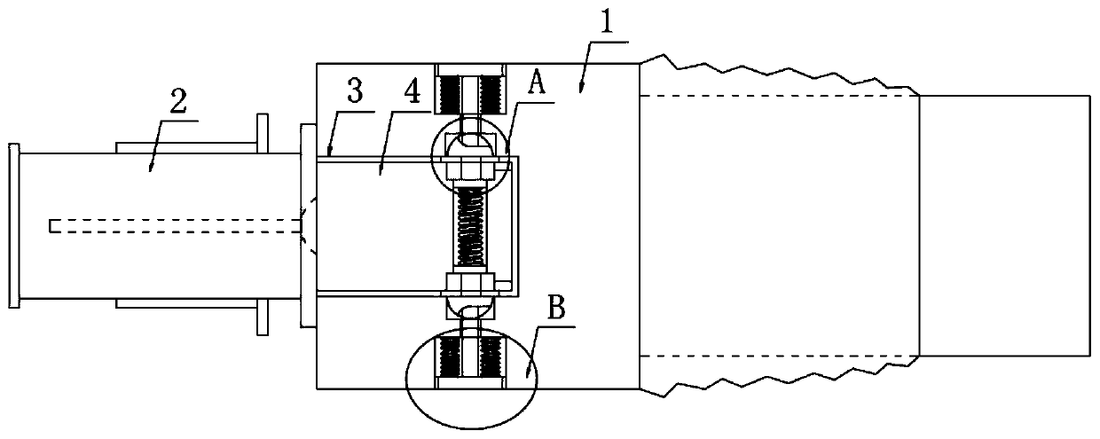
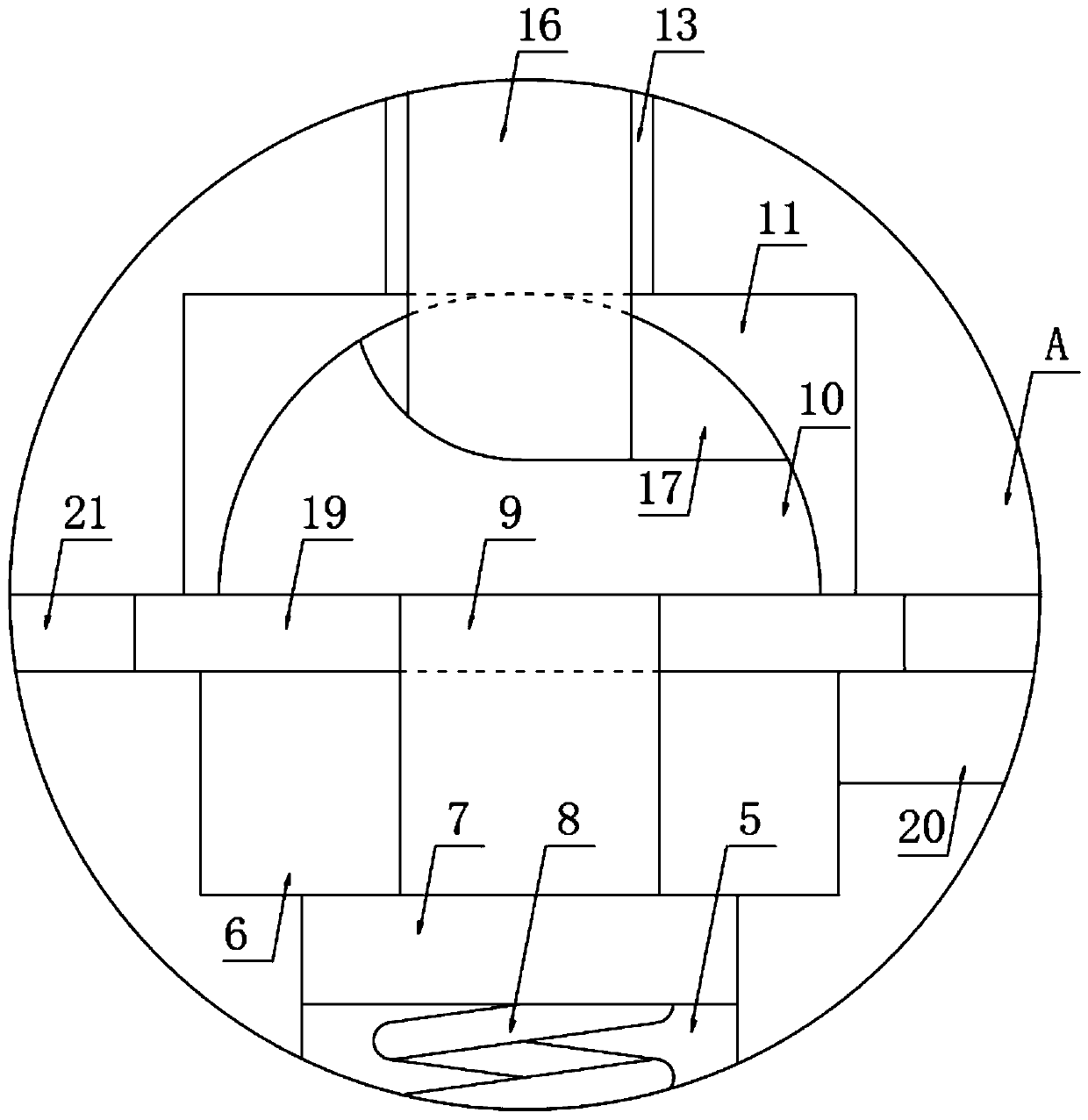
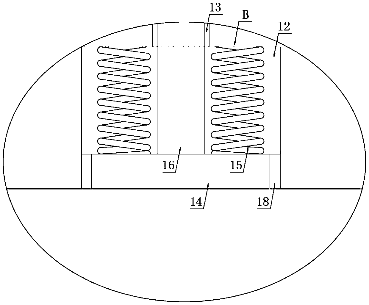
The invention discloses an electric power connecting plug. The connecting plug comprises a base body and a plug. An end surface shape of the base body and the plug is circular. Two positioning groovesare symmetrically arranged in the base body. Two positioning clamps are symmetrically and fixedly installed on the plug. The positioning clamps are clamped in the corresponding positioning grooves. Acavity I and two grooves I are arranged in each of the two positioning clamps. The cavities 1 and the grooves 1 are connected, two sliding blocks are slidably connected in the two cavities 1, a spring 1 is fixedly installed on one sides, close to each other, of the two sliding blocks, and an arc-shaped clamping seat is fixedly installed on one side, away from the spring 1, of each sliding block through a connecting rod. The connecting plug has advantages that the base body and the plug are easy and convenient to disassemble and assemble, the base body and the plug can be fixed or separated quickly, the base body and the plug are fixed more firmly through cooperation of the arc-shaped clamping seat and a clamping groove, and the arc-shaped clamping seat can be moved out from the clamping groove more easily and conveniently through cooperation of a pressing block and a pressing rod.

Description

technical field [0001] The invention relates to a connection plug, in particular to a power connection plug. Background technique [0002] After retrieval, the invention patent with the patent number of CN104953318B discloses a power connection plug, including a base and a plug, the base is connected to the cable, the plug is detachably connected to the base, shallow grooves are provided on both sides of the base, A positioning block is provided in the shallow groove, and positioning clips are provided at corresponding positions on both sides of the plug, and a locking hole is provided at the corresponding position of the positioning clips. [0003] The patent document records in the specification that "the base body 1 is provided with an inner cavity 9, and the inner walls of both sides of the inner cavity 9 are provided with slide grooves 15, and the two sides of the positioning block 6 are provided with sliders 16, and the sliders 16 are arranged on the slider. In the gr...

Claims


Application Information

Patent Timeline
Patent Type & Authority Applications(China)
IPC IPC(8): H01R13/506H01R13/508H01R13/42H01R13/428H01R24/28
CPCH01R13/42H01R13/428H01R13/506H01R13/508H01R24/28
Inventor 艾晓寒
Owner 日照润林电器有限公司
Learn More