
USB integrated circuit

A technology of integrated circuits and circuits, applied in electrical digital data processing, instruments, etc., can solve problems such as power consumption and waste of chip area

Pending Publication Date: 2020-01-14
VIA LABS INC
View PDF14 Cites 0 Cited by
  • Summary
  • Abstract
  • Description
  • Claims
  • Application Information

AI Technical Summary

Problems solved by technology

The idle TX PHY circuit and RX PHY circuit will waste chip area and consume power

Method used


Image

  • USB integrated circuit
  • USB integrated circuit
  • USB integrated circuit

Examples


Embodiment Construction

[0032] As used throughout this specification, including the claims, the term "coupled (or connected)" may refer to any means of connection, direct or indirect. For example, if it is described that a first device is coupled (or connected) to a second device, it should be interpreted that the first device can be directly connected to the second device, or the first device can be connected to the second device through other devices or certain A connection means indirectly connected to the second device. Terms such as "first" and "second" mentioned in the entire description of this case (including the claims) are used to name elements (elements), or to distinguish different embodiments or ranges, and are not used to limit the number of elements The upper or lower limit is not used to limit the order of the elements. In addition, wherever possible, elements / components / steps using the same reference numerals in the drawings and embodiments represent the same or similar parts. Elem...


PUM


Abstract

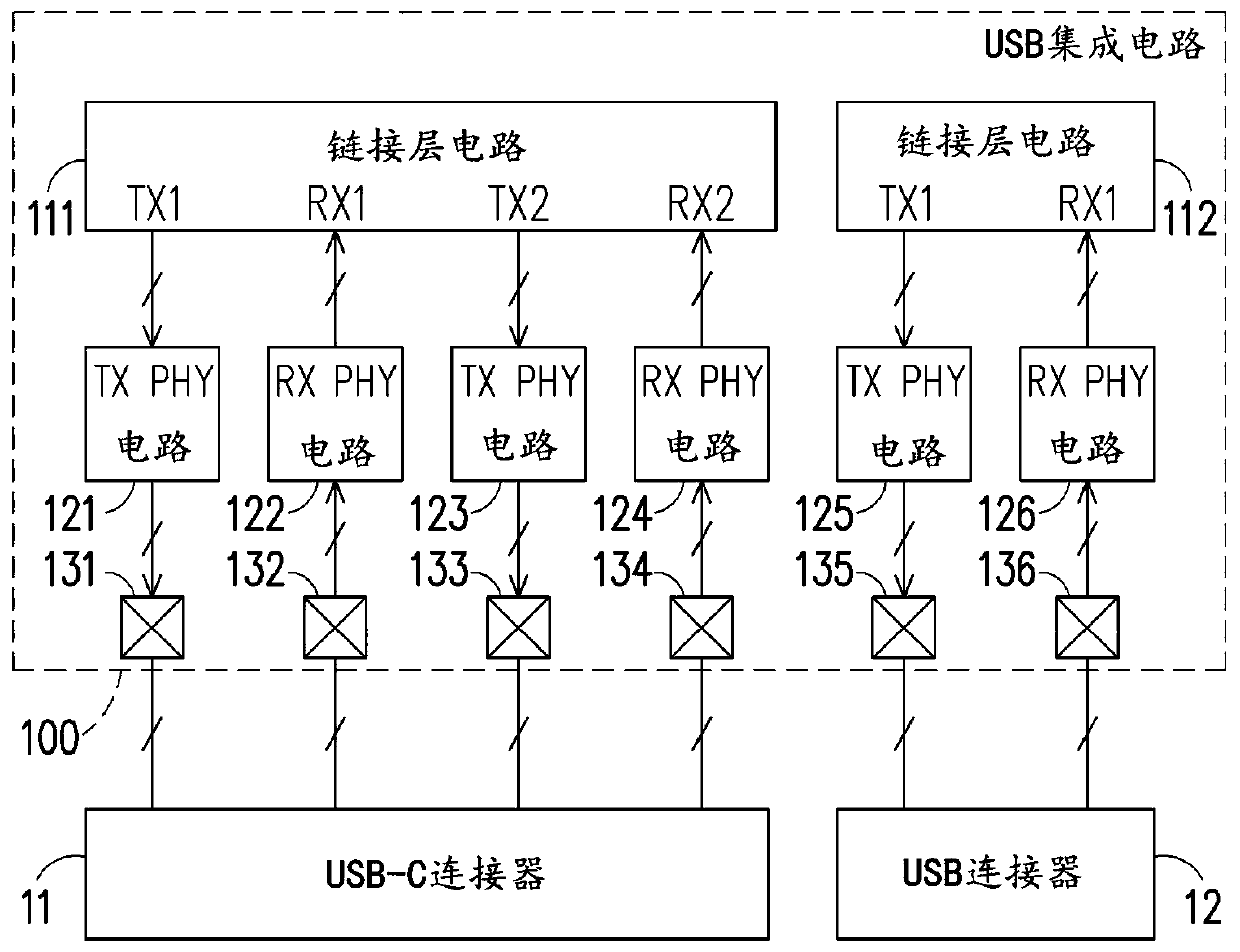
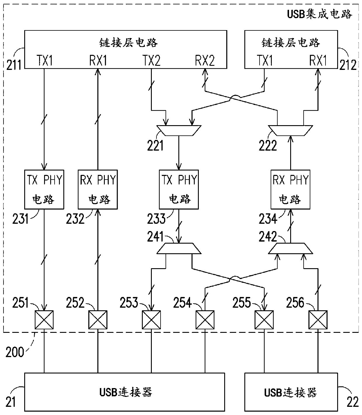
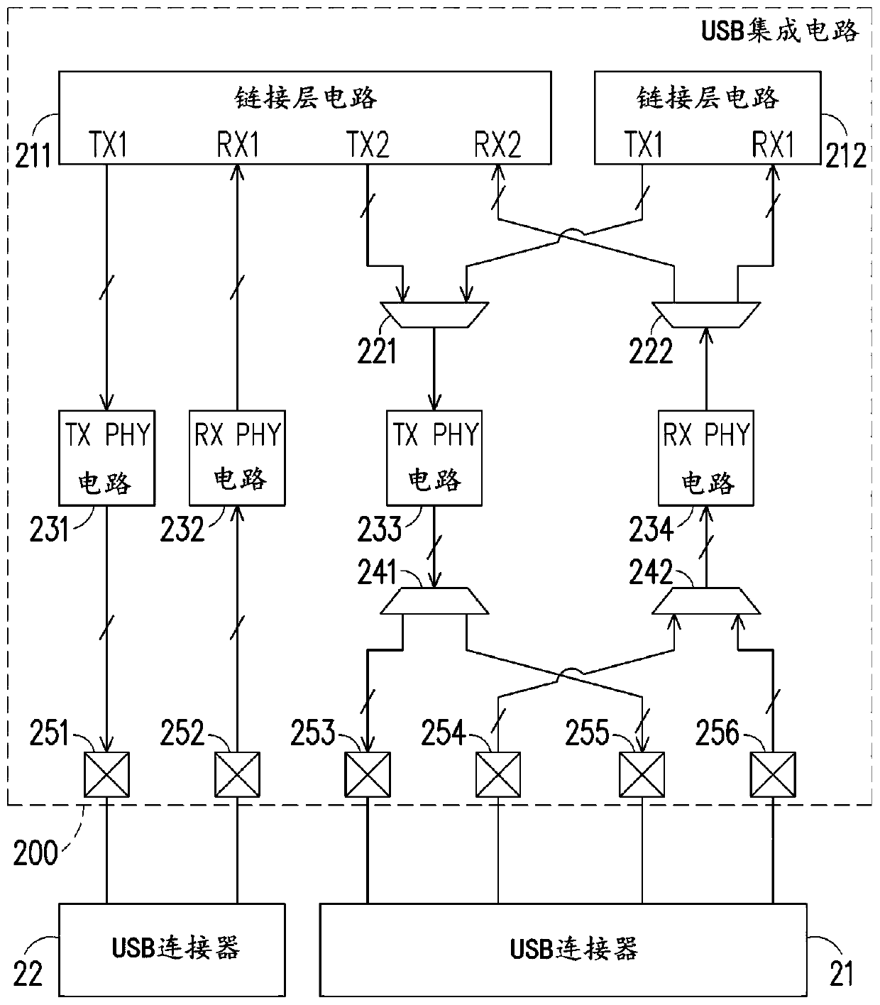
A USB integrated circuit includes three TX connection component pairs and three RX connection component pairs. The first TX connection part pair and the first RX connection part pair are respectivelycoupled with the first TX pin pair and the first RX pin pair of the first USB connector. The second TX connection part pair and the second RX connection part pair are respectively coupled with the first TX pin pair and the first RX pin pair of the second USB connector. The third TX connection component pair is coupled to the second TX pin pair of the first USB connector or to the second TX pin pair of the second USB connector. The third RX connecting part is coupled with the second RX pin pair of the first USB connector or the second RX pin pair of the second USB connector.

Description

technical field [0001] The present invention relates to an electronic circuit, and more particularly to a universal serial bus (hereinafter referred to as USB) integrated circuit. Background technique [0002] USB is a standard for connecting computer systems and external devices. USB 3.1Gen1 uses a single lane, and the transmission speed of this lane is 5Gbps. USB 3.1Gen2 also uses a single channel, and the transmission speed of this channel is 10Gbps. USB 3.2 uses two channels, and the transmission speed of each channel is 10Gbps. Therefore, USB 3.2 can increase the transfer speed to 20Gbps. USB 4.0 also uses two channels, and the transmission speed of each channel is 20Gbps. Therefore, USB 4.0 can increase the transfer speed to 40Gbps. The reason why the transmission speed of USB 3.2 and USB 4.0 can be improved is to improve the usage mode of the USB Type-C connector and accelerate the transmission speed. [0003] The USB Type-C connector has two sets of data transm...

Claims


Application Information

Patent Timeline
IPC IPC(8): G06F13/42
CPCG06F13/4282G06F13/4022G06F13/4068
Inventor 曾纹郁程文豪T.S.石
Owner VIA LABS INC
Learn More