Method for determining maxillofacial cutting path of appliance, cutting method and cutting device

A cutting path and appliance technology, applied in medical science, dentistry, dental drilling, etc., can solve problems such as easy missing teeth, large human factors, unfavorable stable relationship between upper and lower jaws, etc., and achieve precise and controllable cutting paths

Active Publication Date: 2020-01-17
SHANGHAI SMARTEE DENTI TECH CO LTD
View PDF23 Cites 5 Cited by
  • Summary
  • Abstract
  • Description
  • Claims
  • Application Information

AI Technical Summary

Problems solved by technology

[0003] Invisible orthodontic appliances are chosen by more and more people because they are comfortable to wear, can be removed and worn, and are beautiful. Wearing invisible orthodontic appliances during orthodontic treatment requires that they fit closely with the teeth and cooperate with the attachments attached to the teeth for orthodontic treatment. And this kind of invisible orthodontic appliance has a strong wrapping ability for teeth. For teenagers who wear it during the dental replacement period, because it is easy to have missing teeth, during the production process of the invisible orthodontic appliance, this missing part wraps the surface of the gums and wears invisible. Orthodontic appliances take a long time, which is not conducive to the growth of erupted teeth
In addition, when the upper and lower jaws are treated at the same time and the upper and lower jaws need to be coordinated to complete the treatment, since the invisible dental appliance is made of polymer materials, it is easy to produce relative sliding when the upper and lower jaws cooperate, which is not conducive to the establishment of a stable relationship between the upper and lower jaws, especially for When the maxillary teeth are equipped with a jaw pad, the stability of the relative position between the jaw pad and the lower jaw is poor
The current method of making incisions on invisible orthodontic appliances is to manually cut the holes on the braces according to the cutting requirements, but this method has a large human factor, and the differences in individual production lead to uncertainty in the cutting results Sexual factors, the results of the cutting trajectory cannot be effectively controlled

Method used


Image

  • Method for determining maxillofacial cutting path of appliance, cutting method and cutting device
  • Method for determining maxillofacial cutting path of appliance, cutting method and cutting device
  • Method for determining maxillofacial cutting path of appliance, cutting method and cutting device

Examples


Embodiment 1

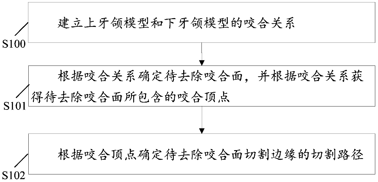
[0069] This embodiment provides a method for determining the maxillofacial cutting path of the appliance, the flow chart of which is as follows figure 1 As shown, it specifically includes the following steps.

[0070] S100: Establish an occlusal relationship between the upper jaw model and the lower jaw model.

[0071] S101: Determine the occlusal surface to be removed according to the occlusal relationship, and obtain occlusal vertices included in the occlusal surface to be removed according to the occlusal relationship.

[0072] S102: Determine the cutting path of the cutting edge of the occlusal surface to be removed according to the occlusal vertex.

[0073] The present invention determines the occlusal surface to be removed and the occlusal vertex contained in the occlusal surface to be removed by establishing an occlusal relationship, automatically performs the fitting of the cutting path according to the occlusal vertex, automatically identifies and determines the tra...

Embodiment 2

[0153] Based on Embodiment 1, this embodiment provides a method for cutting the maxillofacial appliance of an appliance. Based on the method of determining the cutting path on the dental model, the following example will be used to illustrate the cutting of the maxillofacial appliance of the appliance. The flow chart is as follows Figure 12 As shown, it specifically includes the following steps.

[0154] S1201: Determine the cutting path of the cutting edge of the occlusal surface to be removed in the appliance.

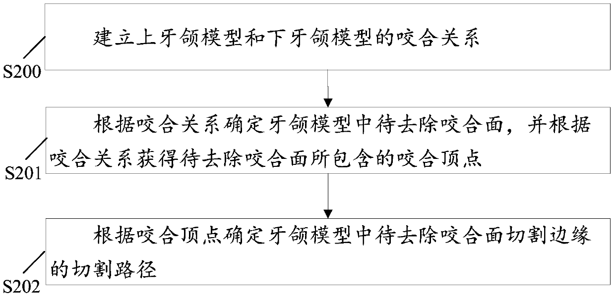
[0155] Step S1201 specifically determines the cutting path based on the mandibular model, which specifically includes the following steps:

[0156] 1) Establish the occlusal relationship between the upper jaw model and the lower jaw model;

[0157] 2) Determine the occlusal surface to be removed in the jaw model according to the occlusal relationship, and obtain the occlusal vertices contained in the occlusal surface to be removed according to the occlusal relation...

Embodiment 3

[0167] Based on Embodiment 1, this embodiment provides a method for cutting the maxillofacial appliance. Based on the method of determining the cutting path on the model of the appliance, the following example will be used to illustrate the cutting of the maxillofacial appliance. The flow chart is as follows Figure 13 As shown, it specifically includes the following steps.

[0168] S1301: Determine the cutting path of the cutting edge of the occlusal surface to be removed in the appliance.

[0169] Step S1301 specifically determines the cutting path based on the lower aligner model, which specifically includes the following steps:

[0170] 1) Establish the occlusal relationship between the upper jaw model and the lower jaw model;

[0171] 2) Obtain the appliance model according to the occlusal relationship between the upper jaw model and the lower jaw model;

[0172] 3) Determine the occlusal surface to be removed in the appliance model according to the occlusal relationshi...


PUM


Abstract

The present invention discloses a method fordetermining a maxillofacial cutting path of an appliance. The method comprises the following steps: establishing an occlusion relation between an upper dental model and a lower dental model; determining an occlusal surface to be removed according to the occlusion relation and obtaining an occlusion peak contained in the occlusal surface to be removed according to the occlusion relation; and determining a cutting path of a cutting edge of the occlusal surface to be removed according to the occlusal peak. The occlusal surface to be removed and the occlusal peak contained in the occlusal surface to be removed are determined by establishing the occlusion relation, the cutting path is automatically fitted according to the occlusal peak, a track needing to be cut isautomatically identified and determined, the cutting path is accurate and controllable and a cutting basis for subsequent laser cutting is provided; and aiming at preparation of the appliance for concave surface malformation correcting, when the appliance after cutting is matched with opposite jaws, relative position between the upper jaw and the lower jaw can be effectively fixed. Aiming at an eruption-assisting application, the occlusal surface of teeth needing to be eruptedout can be correspondingly cut, and guiding out of the eruptedteeth is facilitated.

Description

technical field [0001] The invention relates to the technical field of medical devices, in particular to a method for determining a maxillofacial cutting path of a George appliance appliance, a cutting method and a cutting device. Background technique [0002] Malocclusion refers to the congenital genetic factors or acquired environmental factors during the growth and development of children, such as diseases, bad oral habits, tooth replacement disorders, etc., and can also be caused by trauma, periodontal disease and other reasons after growth and development. Such as irregular arrangement of teeth, abnormal occlusal relationship between the upper and lower dental arches, abnormal size, shape and position of the jaw, facial deformities, etc. The formation factors and mechanisms of malocclusion are complex, and the occurrence process may be caused by a single factor and a single mechanism, or it may be the result of multiple factors or multiple mechanisms. Divided from the ...

Claims


Application Information

Patent Timeline
Patent Type & Authority Applications(China)
IPC IPC(8): A61C7/00A61C7/02A61C19/05A61C1/00G06F30/20
CPCA61C1/0046A61C7/002A61C7/02A61C19/05
Inventor 沈斌杰姚峻峰
Owner SHANGHAI SMARTEE DENTI TECH CO LTD
Why Eureka
Try Eureka