A garment fabric cutting device

A fabric and main body technology, which is applied in the field of clothing fabric cutting devices, can solve the problems of inability to adjust the cutting method and cutting position, and achieve the effect of increasing stability and increasing friction

Active Publication Date: 2020-11-06
湖南浚林服饰有限公司
View PDF1 Cites 2 Cited by
  • Summary
  • Abstract
  • Description
  • Claims
  • Application Information

AI Technical Summary

Problems solved by technology

The cutting body in the above patent has the following disadvantages: the position of the cutting body is fixed, the cutting method is fixed, and the cutting method and cutting position cannot be adjusted according to the shape or material of the actual fabric

Method used


Image

  • A garment fabric cutting device
  • A garment fabric cutting device
  • A garment fabric cutting device

Examples


Embodiment 1

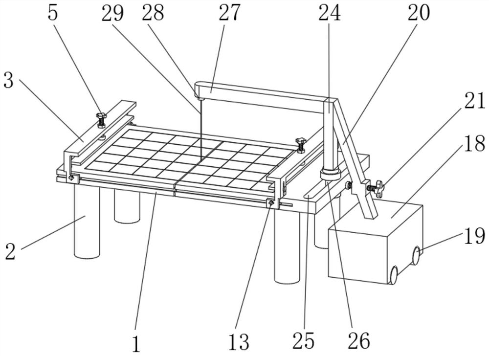
[0030] A clothing cloth cutting device, such as figure 1 , Figure 6 As shown, it includes a main body 1 and a base 18. The top outer wall of the main body 1 is provided with a third sliding groove 25. The bottom outer wall of the main body 1 is welded with four identical support legs 2. The bottom of the base 18 is connected by a shaft. There are four identical base rollers 19, a first connecting frame 20 is welded on the top outer wall of the base 18, a cutting translation column 24 is welded at one end of the first connecting frame 20, and one end of the cutting translation column 24 is connected by a shaft There is a cutting translation pulley 26, the cutting translation pulley 26 is slidably connected to the inner wall of the third chute 25, the outer wall of one side of the cutting translation column 24 is welded with a second connecting frame 27, and the outer wall of the bottom surface of the second connecting frame 27 is connected by a bolt A knife seat 28 is fixed, ...

Embodiment 2

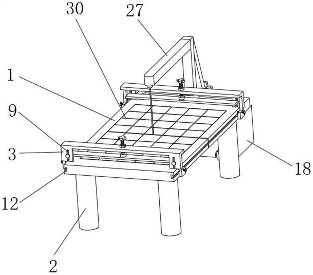
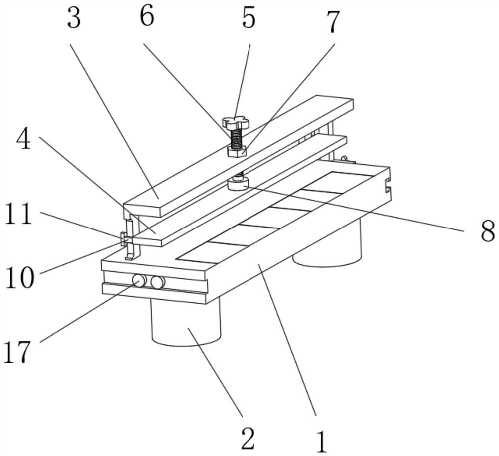
[0041] A clothing cloth cutting device, such as figure 1 As shown, in order to solve the problem of firmness and stability during the use of the pressing plate 4; this embodiment makes the following improvements on the basis of embodiment 1: the outer wall of one side of the pressing plate frame 3 is provided with two identical first slide grooves 9, and the outer wall of one side of the pressing plate 4 is welded with two identical first sliding rods 10, the outer walls of the two first sliding rods 10 are slidingly connected to the inner walls of the two first sliding grooves 9, and one end of the first sliding rod 10 is welded with a pressing plate The limit block 11, by setting the first chute 9 and the first slide rod 10, can play the role of guiding and positioning during the lifting and pressing process of the pressure plate 4, and further limits the level of the pressure plate 4 by setting the pressure plate limit block 11 The displacement in the direction increases th...


PUM


Abstract

The invention discloses a cloth cutting device for clothing manufacture and relates to the technical field of cutting devices. In order to solve the problem of inflexible cutting position, the cloth cutting device for clothing manufacture specifically comprises a main body and a base, wherein a third sliding groove is formed in the outer wall of the top of the main body, four supporting legs whichare the same are welded to the outer wall of the bottom of the main body, four base rollers which are the same are connected to the bottom of the base through shafts, a first connecting frame is welded to the outer wall of the top of the base, and a cutting translation column is welded to one end of the first connecting frame. By arrangement of the third sliding groove, a cutting translation pulley and the base rollers, a cutting translation pulley can slide along the direction of the third sliding groove as required, so that the position of a cutting knife in the horizontal direction is adjusted, and a purpose of cutting materials through a pushing knife in a fixed state is achieved; the cross section of the cutting translation pulley is I-shaped, so that the stability of the cutting translation column in the vertical direction can be improved, and the stability of the cutting knife is improved.

Description

technical field [0001] The invention relates to the technical field of cutting devices, in particular to a clothing fabric cutting device. Background technique [0002] As the top of clothing, food, housing and transportation, there is no doubt that the clothing industry is an eternal sunrise industry, and cloth cutting is an indispensable part of the clothing industry. With the development of science and technology, cloth cutting has changed from manual cutting to machine cutting. [0003] After searching, the Chinese patent application number is CN201720614977.1, which discloses a cloth cutting device, including a cutting body and a cross bar arranged on the cutting body, and a cutting device arranged on the cross bar. The cutting body includes a cutting bracket And the cutting platform arranged on the cutting support, the horizontal ruler of the cutting platform is arranged, the left and right sides of the vertical direction of the cutting platform are provided with round...

Claims


Application Information

Patent Timeline
Patent Type & Authority Patents(China)
IPC IPC(8): D06H7/00
CPCD06H7/00
Inventor 刘桂保刘功林谭件文
Owner 湖南浚林服饰有限公司
Why Eureka
Try Eureka