Supercharge Your Innovation With Domain-Expert AI Agents!

Pantograph/contact network coupling system running test bend and testing method thereof

A technology of running test and coupling system, which is applied in the direction of applying repeated force/pulsation force to test the strength of materials, measuring devices, instruments, etc., which can solve the vibration of the roof, the vibration of the roof in all directions, and the pull-out value of the catenary that cannot be satisfied and other issues to achieve the effect of correct flow quality

Active Publication Date: 2020-01-17
SOUTHWEST JIAOTONG UNIV
View PDF21 Cites 13 Cited by
  • Summary
  • Abstract
  • Description
  • Claims
  • Application Information

AI Technical Summary

Problems solved by technology

[0005] The purpose of the present invention is to provide a pantograph / catenary coupling system operating test bench, which can effectively solve the problem that the existing car-end comprehensive test bench cannot meet the pull-out value of the catenary and the vibration of the roof in all directions question
[0006] Another object of the present invention is to provide a pantograph / catenary coupling system operation test method, which can effectively solve the problem that the existing car-end comprehensive test bench cannot meet the pull-out value of the catenary, and the various directions of the roof Vibration Technical Issues

Method used


Image

  • Pantograph/contact network coupling system running test bend and testing method thereof
  • Pantograph/contact network coupling system running test bend and testing method thereof

Examples


Embodiment approach

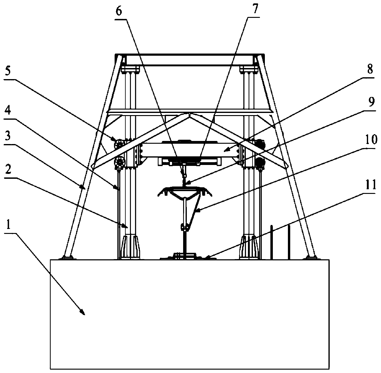
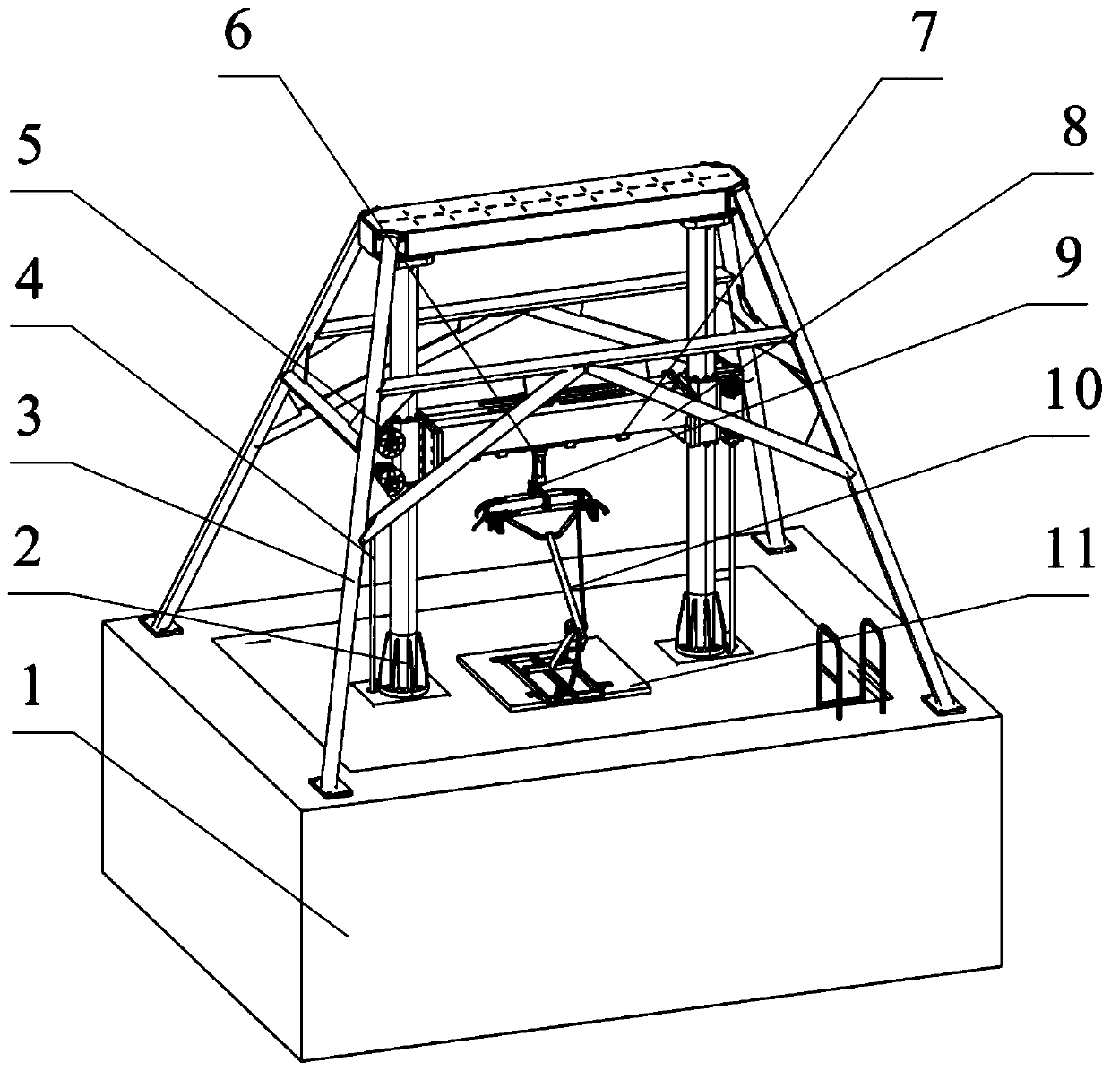
[0023] The purpose of the present invention needs to be implemented through a specific method: a pantograph / catenary coupling system operation test method, while considering the vibration of the vehicle body and the dynamic behavior of the catenary with a pull-out value, the pantograph 10 is tested The pantograph-catenary contact pressure, pantograph 10 and contact line displacement dynamic variation law. A railway pantograph / catenary coupling system dynamic operation simulation test bench for implementing the above-mentioned simulation method is roughly composed of five parts: foundation support, hydraulic system, pantograph under test, vibration excitation system for simulating locomotive vibration and A system for simulating the dynamic behavior of catenaries. The specific implementation is as follows:

[0024] 1. Simulation of vehicle body vibration: The computer controls six hydraulic servo actuators through the hydraulic servo controller, acting on the six-degree-of-fre...


PUM


Abstract

The present invention provides a pantograph / contact network coupling system running test bend and a testing method thereof, and belongs to the technical field of rail traffic bow net simulation test bends. A bottom part of a stand column and an upper surface of a bend base are fixed to form a frame of a gate shape. Flanges are disposed at both ends of a beam, and the beam is fixed with a sliding block in a middle part of a stand column by using a bolt. A locking seat is disposed at an outer side of the sliding block. A vertical motion actuator is disposed in the middle of a bottom part of thebeam. A horizontal motion actuator is disposed at each side of the vertical motion actuator. A force sensor is disposed at a lower end of the vertical motion actuator, and contacts a pantograph bow ofa pantograph. A bottom rack of the pantograph is fixed with an upper surface of a six-degree-of-freedom platform. The six-degree-of-freedom platform is used for implementing a vibration signal of a spatial motion attitude at a train top pantograph base. A D / A board card is used for converting a digital signal into a simulation signal. A hydraulic servo control system is used for inverting a pantograph base motion attitude, and predicting a contact linear displacement of a point at which the pantograph contacts a contact network at a next moment.

Description

technical field [0001] The invention belongs to the technical field of rail transit pantograph-catenary simulation test bench. Background technique [0002] In the electrified railway line, the power supply for vehicle operation and auxiliary equipment lights on the vehicle is obtained through the contact between the pantograph above the vehicle roof and the catenary above the line to take current. A good contact state can ensure stable current reception, while a bad In the contact state, arcing and electric sparks will be generated. In severe cases, the contact wire will be burned. In extreme cases, the pantograph or catenary will be damaged and cause major operational accidents. Therefore, a good contact state is to ensure the safe operation of the vehicle. key. The operating performance and health status of the pantograph and catenary can directly affect the power supply stability of the traction power supply system. Pantograph-catenary dynamic contact force is a key pa...

Claims


Application Information

Patent Timeline
Patent Type & Authority Applications(China)
IPC IPC(8): G01N3/36G01R31/08
CPCG01N3/36G01N2203/0216G01R31/086
Inventor 梅桂明张卫华王江文乔维
Owner SOUTHWEST JIAOTONG UNIV
Features
  • R&D
  • Intellectual Property
  • Life Sciences
  • Materials
  • Tech Scout
  • Unparalleled Data Quality
  • Higher Quality Content
  • 60% Fewer Hallucinations
Learn More