
Mobile hoisting device with accurate matching function for bridge construction

A technology of precise matching and hoisting device, applied in the direction of bridge construction, erection/assembly of bridges, bridges, etc., can solve the problems of bridge steel truss shaking, construction workers' personal safety impact, inability to align bridge steel trusses, etc., and achieve the effect of avoiding shaking.

Active Publication Date: 2020-01-24
ARCHITECTURAL DESIGN RES INST OF GUANGDONG PROVINCE
View PDF9 Cites 1 Cited by
  • Summary
  • Abstract
  • Description
  • Claims
  • Application Information

AI Technical Summary

Problems solved by technology

[0004] The purpose of the present invention is to provide a mobile hoisting device for bridge construction that can be accurately matched, to solve the problem that the bridge construction hoisting device on the market currently proposed by the above-mentioned background technology, in the process of hoisting the bridge steel truss, due to its Steel ropes are used to hoist bridge steel trusses. During hoisting and positioning, the bridge steel trusses are prone to shaking. When splicing and fixing bridge steel trusses, the auxiliary steel ropes on the bridge steel trusses are generally pulled manually for positioning. The bridge steel trusses are swaying, and the bridge steel trusses cannot be aligned accurately at one time, and during the swaying process of the bridge steel trusses, due to the unstable center of gravity of the bridge steel trusses, it is easy to affect the personal safety of construction workers

Method used


Image

  • Mobile hoisting device with accurate matching function for bridge construction
  • Mobile hoisting device with accurate matching function for bridge construction
  • Mobile hoisting device with accurate matching function for bridge construction

Examples


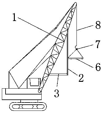
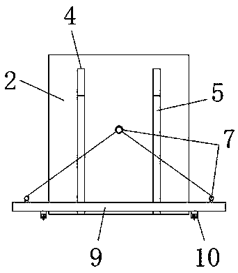
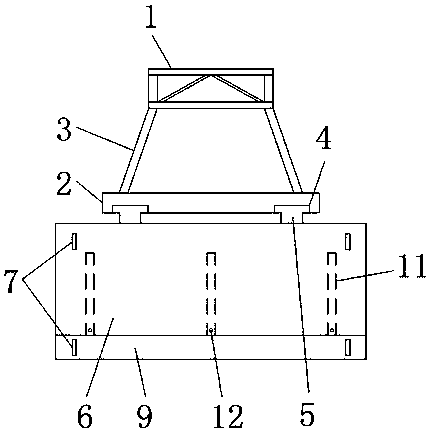
Embodiment Construction

[0027] Based on the embodiments of the present invention, all other embodiments obtained by persons of ordinary skill in the art without making creative efforts belong to the protection scope of the present invention.

[0028] see Figure 1-9 , the present invention provides a technical solution: a mobile hoisting device for bridge construction that can be precisely matched, including a hoisting arm 1, a guide frame 2, a support frame 3, a guide groove 4, a guide column 5, a first hoisting plate 6, Lifting ring 7, lifting steel rope 8, second lifting plate 9, lifting block 10, sliding opening 11, jacking bolt 12, sliding frame 13, support rod 14, sliding groove 15, adjusting groove 16, adjusting block 17, limit Bolts 18 and lifting bolts 19, the front side of the lifting arm 1 is welded with a guide frame 2, and the bottom end of the guide frame 2 is welded to one end of the support frame 3, and the other end of the support frame 3 is welded to the lifting arm 1. The front si...


PUM


Abstract

The invention discloses a mobile hoisting device with the accurate matching function for bridge construction. The mobile hoisting device comprises a hoisting arm, a hoisting ring, a hoisting steel rope and puller bolts, a guide frame is welded to the front side of the hoisting arm, the bottom end of the guide frame is welded and connected to one ends of support frames, the other ends of the support frames are welded and connected to the hoisting arm, guide grooves are formed in the front side of the guide frame, the inner sides of the guide grooves are connected to guide columns in a sliding manner, the puller bolts are arranged at the positions, at the front parts of sliding openings, of a first hoisting plate, adjusting grooves are formed in the lower end surfaces of the first hoisting plate and the second hoisting plate, the inner sides of the adjusting grooves are connected to hoisting blocks through adjusting blocks, limiting bolts are arranged above the interiors of the hoistingblocks, and hoisting bolts are arranged below the interiors of the hoisting blocks. According to the mobile hoisting device with the accurate matching function for bridge construction, the phenomenonthat the first hoisting plate shakes when hoisting a bridge steel truss can be avoided, and stable hoisting of the bridge steel truss is facilitated.

Description

technical field [0001] The invention relates to the technical field of bridges, in particular to a mobile hoisting device for bridge construction that can be precisely matched. Background technique [0002] In the construction process of steel structure bridges, the construction site generally uses cranes to hoist and splice bridge steel trusses for installation. That is, the steel truss of the bridge structure is hoisted to the connecting parts of the bridge that need to be spliced, and combined with the construction workers to use the pulling and guiding connection of the steel rope to realize the alignment of the parts of the bridge steel truss to be installed, and through the installation of the construction workers, to realize the alignment of the bridge steel truss Then, the crane moves on the track of the upper longitudinal girder of the bridge structure, on the ground or on the supporting ship to carry out the hoisting and splicing of the next bridge steel truss. ...

Claims


Application Information

Patent Timeline
Patent Type & Authority Applications(China)
IPC IPC(8): B66C13/08B66C1/12B66C13/06E01D21/00
CPCB66C1/12B66C13/06B66C13/08E01D21/00
Inventor 孙飞
Owner ARCHITECTURAL DESIGN RES INST OF GUANGDONG PROVINCE
Learn More