
Double-group winding machine

A technology of winding machine and winding mechanism, which is applied in coil manufacturing, electrical components, inductance/transformer/magnet manufacturing, etc. It can solve the problems affecting the feeding and winding of the coil skeleton, the support block is easy to wear, and the production efficiency is reduced. , to achieve the effect of reducing space volume and manufacturing cost, saving space volume, and avoiding operation steps

Active Publication Date: 2015-07-01
JIANGSU FEIER ELECTRICAL TECH
View PDF6 Cites 9 Cited by
  • Summary
  • Abstract
  • Description
  • Claims
  • Application Information

AI Technical Summary

Problems solved by technology

[0005] (1) Only one set of wires can be wound. When two coils with different specifications need to be wound, it is necessary to replace the copper wires and re-lead the wires after stopping the machine, which affects the production efficiency of the product;
[0006] (2) The plastic covering frame on the rubber covering mechanism is hinged to the wire feeding frame of the winding mechanism. Shaft, the slider is movably fitted on the shaft and slides up and down with the shaft. There is a horizontal plate at the upper end of the back of the rubber frame, and a support block is installed vertically under the horizontal plate. The support block is installed on the wire feeding frame. The driving cylinder drives it to slide up and down on the shaft, and then approaches or moves away from the skeleton installed on the rotating shaft under the wire feeding frame. The disadvantage of the above-mentioned hinged structure is that the support block and the end of the piston rod of the driving cylinder are embedded and connected. The block is used as the support point for the up and down movement of the rubber frame and the support point for the opening and closing of the rubber frame. After long-term use, the support block is easy to wear, which will cause the winding machine to fail to work normally;
[0007] (3) The existing jig structure needs to use different jigs for coil bobbins, layers and outlet positions of different specifications, and the current jigs can only realize winding, and the clamping and cutting need to be installed on the winding machine The internal wire beam cutter cuts the copper wire without clamping function, which increases the complexity, volume and manufacturing cost of the internal structure of the winding machine;
[0008] (4) The current winding spindle structure has low stability during winding, and after the winding of the current skeleton is completed, the rotation direction of the winding spindle is inconsistent, which affects the feeding and winding of the next batch of coil skeletons, reducing the productivity

Method used

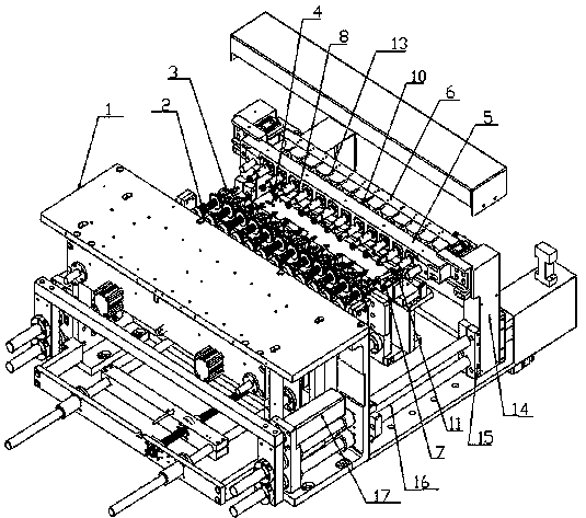
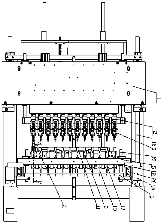
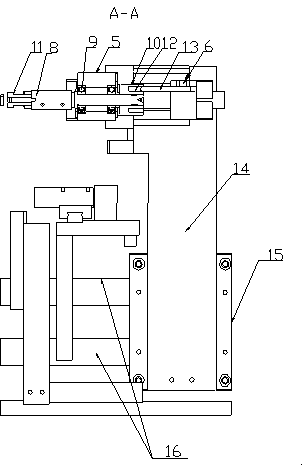

Image

  • Double-group winding machine
  • Double-group winding machine
  • Double-group winding machine

Examples


Embodiment Construction

[0041] Such as Figures 1 to 4 As shown, the present invention discloses a double-group winding machine, which includes a frame 1, several winding spindles 2 equidistant and horizontally installed on the front side of the frame 1, a double-group winding mechanism above the frame 1 and a package The glue mechanism, the feeding mechanism directly in front of the frame 1, each winding spindle 2 is equipped with a fixture 3 for installing the coil skeleton 62, the feeding mechanism, the double-set winding mechanism and the rubber covering mechanism are respectively connected to the winding spindle The jig 3 on the 2 cooperates to realize feeding, double-group winding and rubber encapsulation.

[0042] The feeding mechanism includes a feeding plate 4 directly in front of the frame 1 and a skeleton mounting seat B installed on the feeding plate 4 and corresponding to the winding main shaft 2 one by one. The upper end surface of each skeleton mounting seat B has a The coil frame ins...


PUM


Abstract

The invention relates to a double-group winding machine. The machine comprises a first rack, a plurality of main winding shafts which are horizontally mounted at equal intervals on the front side of the rack, a double-group winding mechanism, a glue covering mechanism, and a feeding mechanism in the front of the rack, wherein the double-group winding mechanism and the glue covering mechanism are arranged above the rack; each main winding shaft is provided with a jig provided with a coil framework; the feeding mechanism, the double-group winding mechanism and the glue covering mechanism are respectively matched with the jigs on the main winding shafts to perform feeding, double-group winding and glue covering. The machine has the advantages that all mechanisms are reasonably arranged and matched, so that the structure is compact, the service life is long, and the production efficiency of a product is increased.

Description

technical field [0001] The invention relates to a winding machine, in particular to a double-group winding machine. Background technique [0002] Electrical products use quite a lot of electromagnetic components, and the main structure of electromagnetic components is various types of coils. Transformers of various sizes, mid-circumference and inductance coils for radios, speakers, earphones, voice coils for microphones, etc., all of these coils need to be wound by winding machines. [0003] With the rapid development of electronic technology, various household appliances and electronic equipment emerge in an endless stream, and their performance is also constantly improving. Therefore, the demand for electronic transformers and inductors of various specifications is increasing. The design requirements such as the number of coil turns, the number of layers, the position of the outlet, the number of layers and methods of the rubber coating are also different. [0004] In th...

Claims


Application Information

Patent Timeline
IPC IPC(8): H01F41/06H01F41/12H01F41/09H01F41/096H01F41/098
Inventor 张云飞
Owner JIANGSU FEIER ELECTRICAL TECH
Learn More