Compressed garbage truck

A garbage truck and compression type technology, which is applied in the directions of garbage receptacle, transportation and packaging, can solve the problems of energy consumption of hydraulic system and unfavorable efficient utilization of energy, and achieve the effect of improving compression efficiency and reducing the number of repeated compressions.

Inactive Publication Date: 2020-01-31
LIXIN COUNTY YURUO INFORMATION TECH CO LTD
View PDF0 Cites 0 Cited by
  • Summary
  • Abstract
  • Description
  • Claims
  • Application Information

AI Technical Summary

Problems solved by technology

At present, one of the garbage trucks we know is the backward garbage type compression garbage truck. The disadvantage is that the garbage needs to be compressed over and over again. The previously compressed garbage needs to be compressed again after the new garbage is put into it. Consumes too much energy of the hydraulic system, which is not conducive to the effective use of energy

Method used


Image

  • Compressed garbage truck
  • Compressed garbage truck
  • Compressed garbage truck

Examples


specific Embodiment 1

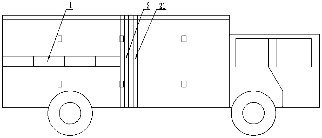
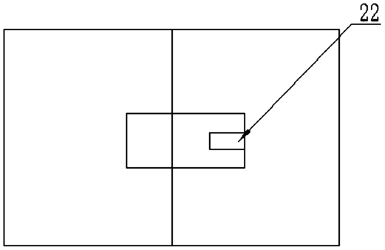
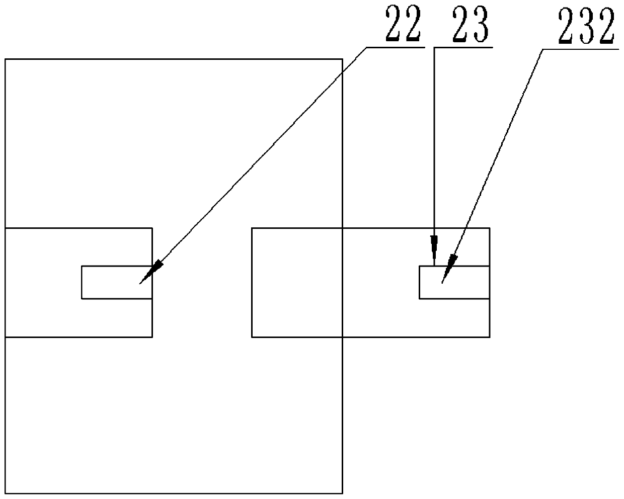
[0018] A compression garbage truck is provided based on the above purpose, the compression garbage truck includes a head and a carriage, and a compression module is arranged behind the carriage. The compression module includes a hydraulic compression rod 1 and an extruding plate 2 arranged at the end of the hydraulic compression rod 1; the extruding plate 2 protects the multi-layer sub-pressing plate 21 stacked on top of each other, and the side of the sub-pressing plate 21 facing the direction of the front of the vehicle is provided with a convex Out of the buckle, the side of the sub-press plate 21 facing away from the direction of the front of the car is provided with a groove that cooperates with the protruding buckles of other sub-press plates 21; the side wall of the groove is provided with a locking groove 22, and the side wall of the protruding buckle is provided with There is a receiving hole 23, and a movable block 232 cooperating with the locking groove 22 is arrange...

specific Embodiment 2

[0023] Further, in order to be able to identify the alignment time of the receiving groove 24 and the positioning hole and control the time window for separating the adjacent sub-press plate 21, a slide rail is provided on the inner top of the compartment, and an insertion slide rail is provided on the top of the sub-press plate 21 There are several trigger switches in the slide rail, the number of rows of trigger switches is the same as that of positioning holes, the vertical plane of the row of trigger switches coincides with the vertical plane of the row of positioning holes, and the trigger switches are respectively connected to the The two telescopic rods are electrically connected with the pressure sensor. When the pressure sensor detects that the pressure received by the outermost sub-platen 21 reaches the set reset value, when the trigger switch is touched by the slider, the trigger switch controls the extension of the second telescopic rod, and the positioning block 24...


PUM


Abstract

The invention discloses a compressed garbage truck, belongs to the technical field of garbage transportation equipment, and effectively improves the garbage compression efficiency. The compressed garbage truck comprises a truck head and a carriage; a compression module is arranged behind the carriage; the compression module comprises a hydraulic compression rod, and an extrusion plate arranged atthe end part of the hydraulic compression rod; the extrusion plate comprises multiple layers of laminated sub pressing plates; the sub pressing plates are detachably connected; multiple positioning holes are formed in the internal side wall of the carriage; accommodating tanks are arranged on the two sides of the sub pressing plates; second extension rods and positioning blocks are arranged in theaccommodating tanks; and the two ends of the second extension rods are connected with the positioning blocks and the bottoms of the accommodating tanks. Through separation and positioning of the subpressing plates, after compressed garbage is limited in fixed space, subsequent garbage is compressed again, so that the repeated compression times of garbage are reduced, and the compression efficiency is effectively improved.

Description

technical field [0001] The invention relates to the technical field of garbage transportation equipment, in particular to a compression garbage truck. Background technique [0002] Urban waste collection and transportation is a major event related to keeping people's living environment clean and hygienic, and it is also an essential thing. At present, one of the garbage trucks we know is the backward garbage type compression garbage truck. The disadvantage is that the garbage needs to be compressed over and over again. It consumes too much energy of the hydraulic system, which is not conducive to the effective utilization of energy. Contents of the invention [0003] In view of this, the purpose of the present invention is to propose a compressed garbage truck, through the separation and positioning of the sub-platen, the compressed garbage is limited in a fixed space, and the subsequent garbage is re-compressed, thereby reducing the waste of repeated compression. The nu...

Claims


Application Information

Patent Timeline
Patent Type & Authority Applications(China)
IPC IPC(8): B65F3/14B65F3/00
CPCB65F3/00B65F3/14B65F2003/006
Inventor 刘杰张若玉
Owner LIXIN COUNTY YURUO INFORMATION TECH CO LTD
Why Eureka
Try Eureka