Outer yarn rack device for automatically changing yarns

A creel, automatic technology, applied in the direction of piecing device, spinning machine, continuous winding spinning machine, etc., can solve the problems of human injury, personal safety hazards of staff, etc., to avoid safety hazards, realize full automation, The effect of increasing automation penetration

Pending Publication Date: 2020-01-31
YICHANG JINGWEI TEXTILE MACHINERY
View PDF0 Cites 4 Cited by
  • Summary
  • Abstract
  • Description
  • Claims
  • Application Information

AI Technical Summary

Problems solved by technology

[0005] Aiming at the deficiencies in the prior art, the present invention provides an automatic yarn-changing outer creel device, which is used to solve the problem that yarn rolls must be manually replaced in existing textile equipment that needs to use yarns. There is a certain hidden danger to the personal safety of the staff when the yarn roll is placed, and at the same time, it will cause damage to the human body after working for a long time

Method used


Image

  • Outer yarn rack device for automatically changing yarns
  • Outer yarn rack device for automatically changing yarns
  • Outer yarn rack device for automatically changing yarns

Examples


Embodiment 1

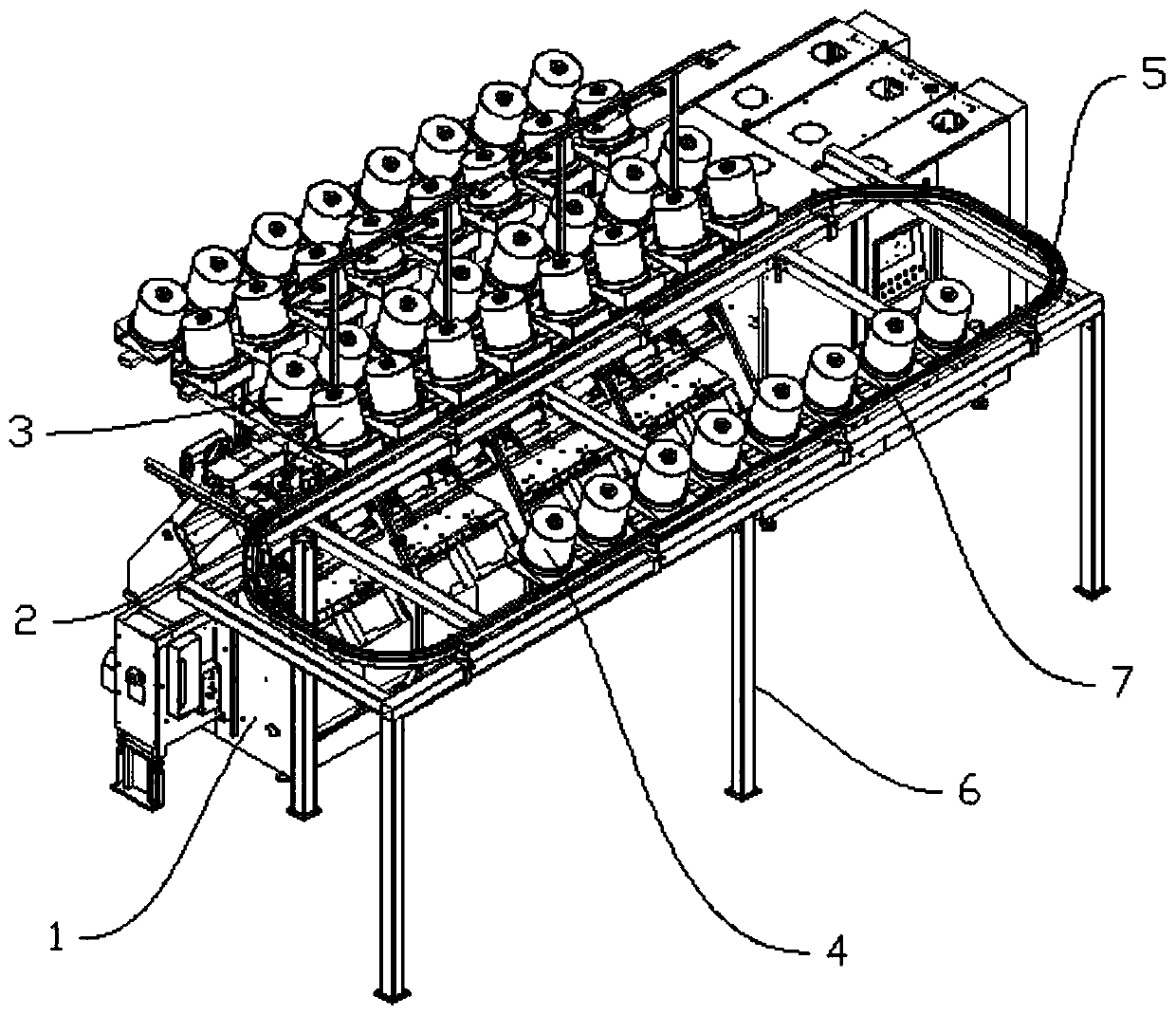
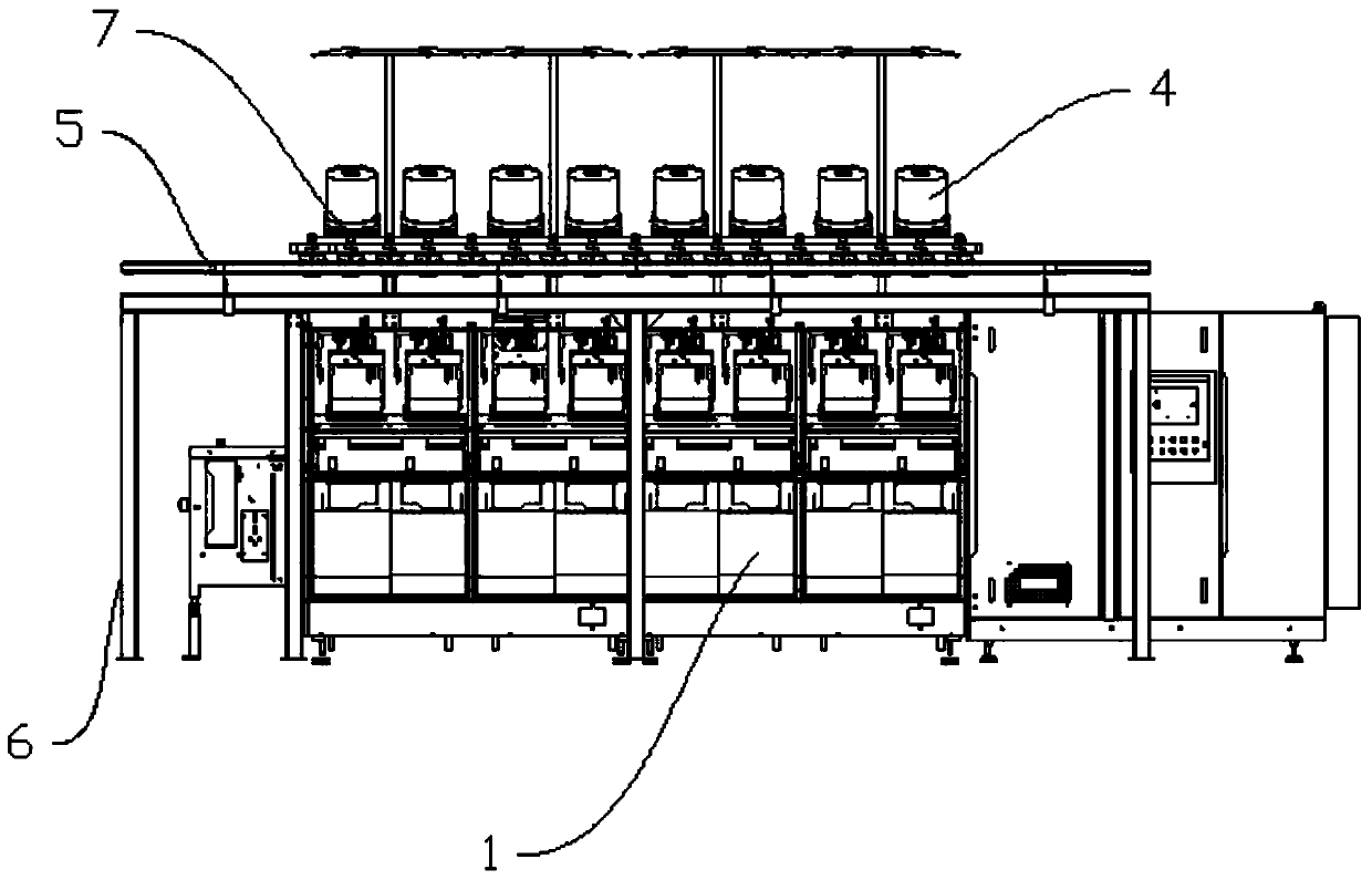
[0028] Such as Figure 1-4 As shown, the present invention proposes an outer creel device for automatic yarn change. The outer creel device of the present invention is used in conjunction with the main machine 1 that needs to be loaded with yarn. Several yarn feeding mechanisms are arranged side by side, and each yarn feeding mechanism includes two outgoing yarn reels 2 and a discharge spindle, wherein the two yarn reels 2 are arranged up and down, and the discharge spindle is arranged in the middle of the two yarn reels 2, Thereby saving space. The yarn reels 2 positioned above in each yarn feeding mechanism on the top of the main frame 1 have just formed a row of yarn reels 2 arranged in a straight line. And because each yarn roll 2 is provided with a spare yarn roll 3, then the top of the main frame 1 also has a row of spare yarn rolls 3 arranged side by side with the original yarn roll 2. In this embodiment, the main machine 1 includes yarn feeding mechanisms arranged si...

Embodiment 2

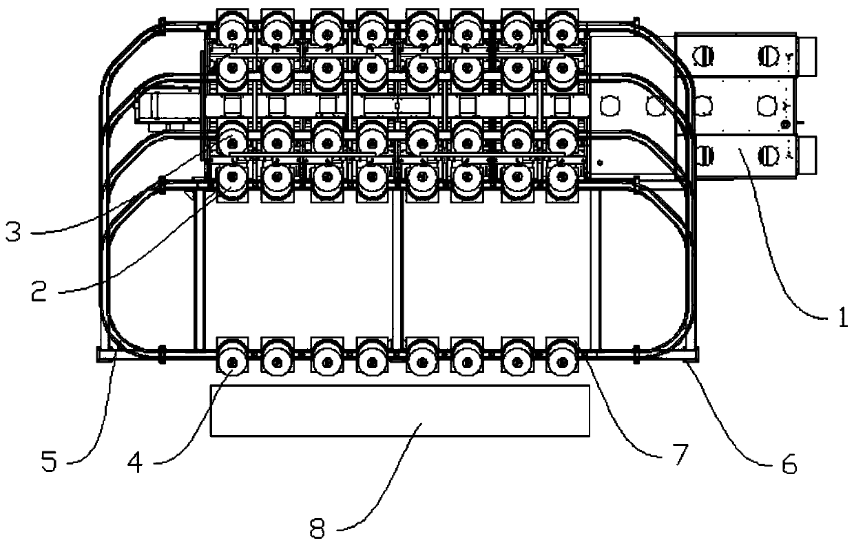
[0038] Such as Figure 5 As shown, the remaining parts in this embodiment are the same as in Embodiment 1, the difference is that the guide rail 5 exists between the different main machines 1 arranged in parallel, and corresponds to the yarn roll 2 and the spare yarn on each main machine 1. The guide rail 5 of roll 3 is bent and merged in the same direction at both ends to form a plurality of partially overlapping annular structures, so that all the main machines 1 in the factory can be simultaneously replaced by yarn roll 2 to further improve efficiency.


PUM


Abstract

The invention provides an outer yarn rack device for automatically changing yarns. A yarn feeding device is used in coordination with a host machine requiring yarn feeding; a plurality of yarn feedingmechanisms are sequentially arranged on the host machine along the horizontal direction; yarn rolls and spare yarn rolls are arranged at the front and back of the top of the yarn feeding mechanisms;the yarn feeding device comprises a vertically-arranged bracket and a closed guide rail formed in the top of the bracket; the guide rail respectively passes through the positions of the yarn rolls andthe spare yarn rolls at the top of the host machine when working; the yarn rolls are flexibly mounted on the guide rail and can move along the guide rail; and a yarn roll changing mechanism is further arranged on the guide rail. The changing yarn rolls are moved through the guide rail, and thus manual picking and placing operations are avoided, so that the potential safety hazard of picking and placing heavy objects at higher places is avoided, and the problem of damaging the health of a worker under long-term work is further solved; accordingly, the manual operation is liberated, the labor cost can further be reduced, the automation popularization rate of a production workshop is improved, and the full automation of yarn feeding operation is realized.

Description

technical field [0001] The invention relates to the field of textile equipment, in particular to an outer creel device capable of automatically changing yarns. Background technique [0002] The textile industry is one of the important light industries that are indispensable in modern times, and yarn is the most basic raw material in the textile industry. Through the processing of yarn, it can be made into different specifications of lines, which can be used for weaving and rope making , thread making, knitting and embroidery and other different textile crafts. [0003] The machinery for yarn processing in the modern textile industry includes yarn doubling frames, twisting machines, winding machines, etc. These devices usually include a main machine and a main yarn roll set on the main machine for yarn loading, and each main yarn roll is A spare yarn roll is set up, and the thread head of the spare yarn roll is connected to the thread end of the main yarn roll. When the yarn...

Claims


Application Information

Patent Timeline
Patent Type & Authority Applications(China)
IPC IPC(8): D01H9/02D01H9/18D01H1/16D01H15/00
CPCD01H1/16D01H9/02D01H9/18D01H15/00
Inventor 汪斌肖明聂俭李明光张焕军吴磊
Owner YICHANG JINGWEI TEXTILE MACHINERY
Why Eureka
Try Eureka