Oil and gas pipeline non-stop transmission on-line desanding device

A technology for oil and gas pipelines and sand storage. It is applied to the feeding/discharging device of the settling tank, the mining fluid, and the separation of sediments by centrifugal force. It can solve the problems of poor separation effect and complicated installation, and achieve high separation efficiency and high separation efficiency. effective way

Inactive Publication Date: 2020-01-31
LUOYANG PETROCHEMICAL ENG CORP SINOPEC +1
View PDF13 Cites 3 Cited by
  • Summary
  • Abstract
  • Description
  • Claims
  • Application Information

AI Technical Summary

Problems solved by technology

[0005] The present invention provides a new on-line desanding device technology for non-stop transmission of oil and gas pipelines in view of the shortcomings of the prior art such as complicated installation and poor separation effect. Or installed vertically, does not take up extra space, does not require auxiliary facilities, and has high separation efficiency. It can efficiently separate solid impurities in oil and gas, and at the same time, the process of cleaning sand does not affect the normal transportation of pipelines.

Method used


Image

  • Oil and gas pipeline non-stop transmission on-line desanding device
  • Oil and gas pipeline non-stop transmission on-line desanding device
  • Oil and gas pipeline non-stop transmission on-line desanding device

Examples


Embodiment Construction

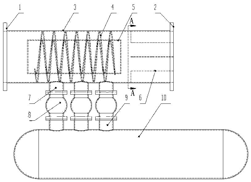
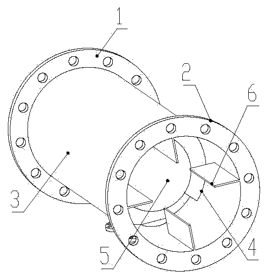
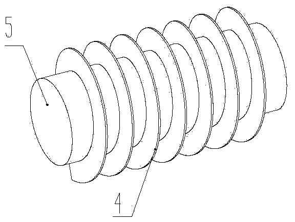
[0021] See attached Figure 1~4 , an oil and gas pipeline non-stop on-line desanding device, comprising a desandering device inlet 1, a desandering device cylinder 3, a columnar cylinder 5, a spiral blade 4, an anti-rotation fan plate 6, a sand discharge port 7, a full diameter The ball valve 8 and the outlet 2 of the sand removal device, wherein the cylinder body 3 of the sand removal device is a cylindrical structure with flange joints at both ends. The two flange joints are respectively the inlet 1 of the sand removal device and the outlet 2 of the sand removal device. The cylinder 5 is located inside the cylinder body 3 of the sand removal device and is installed coaxially with the cylinder body 3 of the sand removal device, and the spiral blade 4 is located in the annular space between the cylinder body 3 of the sand removal device and the cylindrical cylinder 5 to form a spiral flow channel; The plates 6 are located in the cylinder body 3 of the sand removal device, inst...


PUM


Abstract

The invention discloses an oil and gas pipeline non-stop transmission on-line desanding device and aims to overcome the defects that in the prior art, installation is complicated, and the separation effect is poor. The desanding device comprises a desanding device inlet, a desanding device outlet, a desanding device cylinder, a columnar cylinder, a helical blade, rotation-stopping fan-shaped plates, sand discharging outlets and full-bore ball valves, wherein the columnar cylinder is in the desanding device cylinder, the columnar cylinder is coaxial to the desanding device cylinder body, the helical blade is located in an annular space between the desanding device cylinder and the columnar cylinder to form a helical flow channel, the rotation-stopping fan-shaped plates are in the desandingdevice cylinder, the sand discharging outlets are formed in the lower side of the desanding device cylinder in a row, and the sand discharging outlets run through the full-bore ball valves and sand inlets in sequence to be communicated with a sand storage chamber. By means of the oil and gas pipeline non-stop transmission on-line desanding device, the installation way of the desanding device is identical to that of a common valve, the desanding device can be horizontally or vertically installed and occupies little space, auxiliary facilities are not needed, the separation efficiency is high, solid impurities in oil and gas can be efficiently separated out, and normal pipeline transportation is not affected in the sand cleaning process.

Description

technical field [0001] The invention belongs to the technical field of centrifugal separation and flow guarantee, and relates to an on-line desanding device for oil and gas pipelines without transmission. Background technique [0002] In the process of oil and gas extraction, it is inevitable that there will be solid impurities such as mud and sand, especially with the application of new technologies such as hydraulic fracturing and polymer flooding, this phenomenon has become increasingly serious. [0003] The existence of solid impurities will adversely affect the normal operation of downstream oil and gas treatment facilities such as three-phase separators, and cause strong wear and tear on the inner anti-corrosion layer on the inner wall of the pipeline. The normal operation of pumps and compressors in power facilities is highly sensitive to solid impurities. Advanced solid-liquid and gas-solid separation facilities are of great significance. At present, the main method...

Claims


Application Information

Patent Timeline
Patent Type & Authority Applications(China)
IPC IPC(8): E21B43/34B01D21/26B01D21/24
CPCB01D21/245B01D21/262E21B43/34
Inventor 王以斌姚建军常征王文昊李战杰何龙辉李津王惠勤杜富国
Owner LUOYANG PETROCHEMICAL ENG CORP SINOPEC
Why Eureka
Try Eureka