Full-diameter pipeline type sand removing device

A full-bore, pipeline-type technology, applied in wellbore/well components, separation methods, gas fuels, etc., can solve problems such as poor separation effect and complicated installation, achieve high separation efficiency, simplify bypass design, and separate methods. efficient effect

Active Publication Date: 2020-01-31
SINOPEC GUANGZHOU ENG +1
View PDF7 Cites 0 Cited by
  • Summary
  • Abstract
  • Description
  • Claims
  • Application Information

AI Technical Summary

Problems solved by technology

[0007] The present invention provides a full-diameter pipeline type sand removal device for the disadvantages of complicated installation and poor separation effect in the prior art. Using the technology of the present invention, solid impurities in natural gas can be efficiently separated, and at the same time, it is convenient for pigging during the pigging process. through the

Method used


Image

  • Full-diameter pipeline type sand removing device
  • Full-diameter pipeline type sand removing device
  • Full-diameter pipeline type sand removing device

Examples


Embodiment Construction

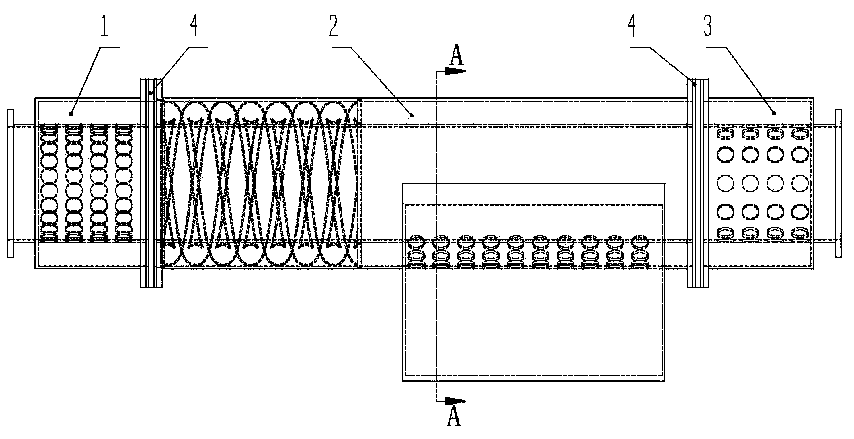
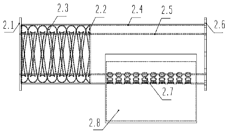
[0033] See attached Figure 1-10, a full-bore pipeline type desanding device of the present invention, comprising a flow direction adjustment inlet 1, a swirl flow sand removal section 2 and a flow direction adjustment outlet 3, the three are connected and formed according to the fluid flow sequence, the flow direction adjustment inlet 1 and the swirl flow Partition plates 4 are set between the desanding section 2 and between the swirl desanding section 2 and the flow direction adjustment outlet 3, and the flow direction adjustment inlet 1 is a structure formed by nesting the flow direction adjustment inlet inner cylinder 1.2 and the flow direction adjustment inlet outer cylinder 1.3 The flow direction adjustment inlet inner cylinder 1.2 is coaxially arranged with the flow direction adjustment inlet outer cylinder 1.3, the inlet end of the flow direction adjustment inlet inner cylinder 1.2 is the natural gas inlet 1.1, and the flow direction adjustment inlet inner cylinder 1.2 ...


PUM

PropertyMeasurementUnit
diameteraaaaaaaaaa
diameteraaaaaaaaaa
diameteraaaaaaaaaa

Abstract

The invention discloses a full-diameter pipeline type sand removing device. The device comprises a flow direction adjusting inlet, a cyclone sand removing section and a flow direction adjusting outlet, wherein partition plates are arranged between the flow direction adjusting inlet and the cyclone sand removing section and between the cyclone sand removing section and the flow direction adjustingoutlet, the flow direction adjusting inlet is of a structure formed by mutually nesting a flow direction adjusting inlet inner cylinder and a flow direction adjusting inlet outer cylinder, the cyclonesand removing section is of a structure formed by mutually nesting a cyclone section outer cylinder and a cyclone section inner cylinder, a double spiral pipe is arranged at the inlet end of an annular space formed between the cyclone section outer cylinder and the cyclone section inner cylinder, the bottom, at the the downstream of the double spiral pipe, of the outer cylinder of cyclone sand removing section is provided with sand discharging holes which are uniformly arranged, in the normal sand removing process, the partition boards are isolating blind plates, and in the case of a pipe cleaning, the partition boards are full-diameter backing plates. According to the device, when the sand removing device is used, the installation mode of the sand removing device is the same as a commonvalve, the device can be installed in a horizontal or vertical direction, extra space is not occupied, auxiliary facilities are not needed, the separation efficiency is high, solid impurities in oil and gas can be can effectively separated, and meanwhile, normal conveying of the pipeline in the process of cleaning the sand is not affected.

Description

technical field [0001] The invention belongs to the technical field of centrifugal separation and flow guarantee, and relates to a full-diameter pipeline type desanding device. Background technique [0002] The characteristics of natural gas determine that natural gas pipeline transportation is more economical and reliable than other transportation methods, and it is currently the main method of onshore natural gas transportation. The main sources of liquid and solid impurities in the natural gas transmission system include: condensate oil, condensate water, and cuttings dust brought downhole during gas production; dirt and residue left during pipeline construction; iron filings and corrosion products in the pipeline . [0003] Dust particles such as sand and rust move with the high-speed air flow, which will cause strong abrasion to the inner wall of the pipeline. As the main power equipment in the gas transmission process, the compressor has strict requirements on the con...

Claims


Application Information

Patent Timeline
Patent Type & Authority Applications(China)
IPC IPC(8): E21B43/34B01D45/16C10L3/10
CPCE21B43/34B01D45/16C10L3/101
Inventor 王以斌姚建军常征王文昊李战杰何龙辉李津王惠勤杜富国
Owner SINOPEC GUANGZHOU ENG
Why Eureka
Try Eureka