
Shell structure of electronic equipment and electronic equipment

A technology of electronic equipment and shell structure, which is applied in the shell structure of electronic equipment and the field of electronic equipment, which can solve the problems of rising material costs and installation costs of electronic equipment, destroying the shape of electronic equipment, and poor viewing experience, etc., to achieve improved appearance structure, saving labor cost, concealed effect of dismantling position

Active Publication Date: 2020-01-31
GEER TECH CO LTD
View PDF23 Cites 2 Cited by
  • Summary
  • Abstract
  • Description
  • Claims
  • Application Information

AI Technical Summary

Problems solved by technology

In the installation of traditional electronic equipment enclosures, the most commonly used connection method is screw connection. Although the screw connection is simple, standardized, and high in stability, the screws on the appearance destroy the overall shape of the electronic equipment, giving people a bad feeling. viewing experience
At the same time, the separate installation of multiple screws also requires more manual operations. Therefore, in today's rising labor costs, the increase in the number of screws also means the increase in the cost of electronic equipment materials and installation costs.

Method used


Image

  • Shell structure of electronic equipment and electronic equipment
  • Shell structure of electronic equipment and electronic equipment
  • Shell structure of electronic equipment and electronic equipment

Examples


Embodiment Construction

[0025] In order to make the object, technical solution and advantages of the present invention clearer, the implementation manner of the present invention will be further described in detail below in conjunction with the accompanying drawings.

[0026] In the description of this application, it should be noted that the terms "center", "upper", "lower", "left", "right", "vertical", "horizontal", "inner", "outer" etc. The indicated orientation or positional relationship is based on the orientation or positional relationship shown in the drawings, and is only for the convenience of describing the present application and simplifying the description, rather than indicating or implying that the referred device or element must have a specific orientation, use a specific orientation construction and operation, therefore should not be construed as limiting the application. In addition, the terms "first", "second", and "third" are used for descriptive purposes only, and should not be co...


PUM


Abstract

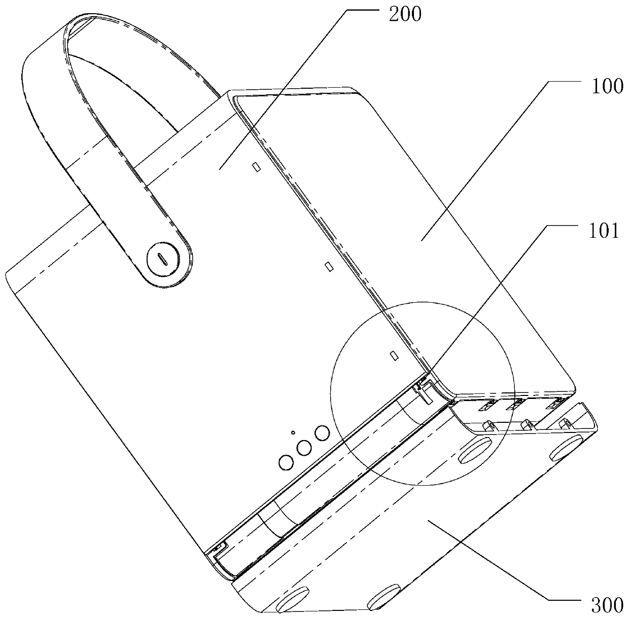
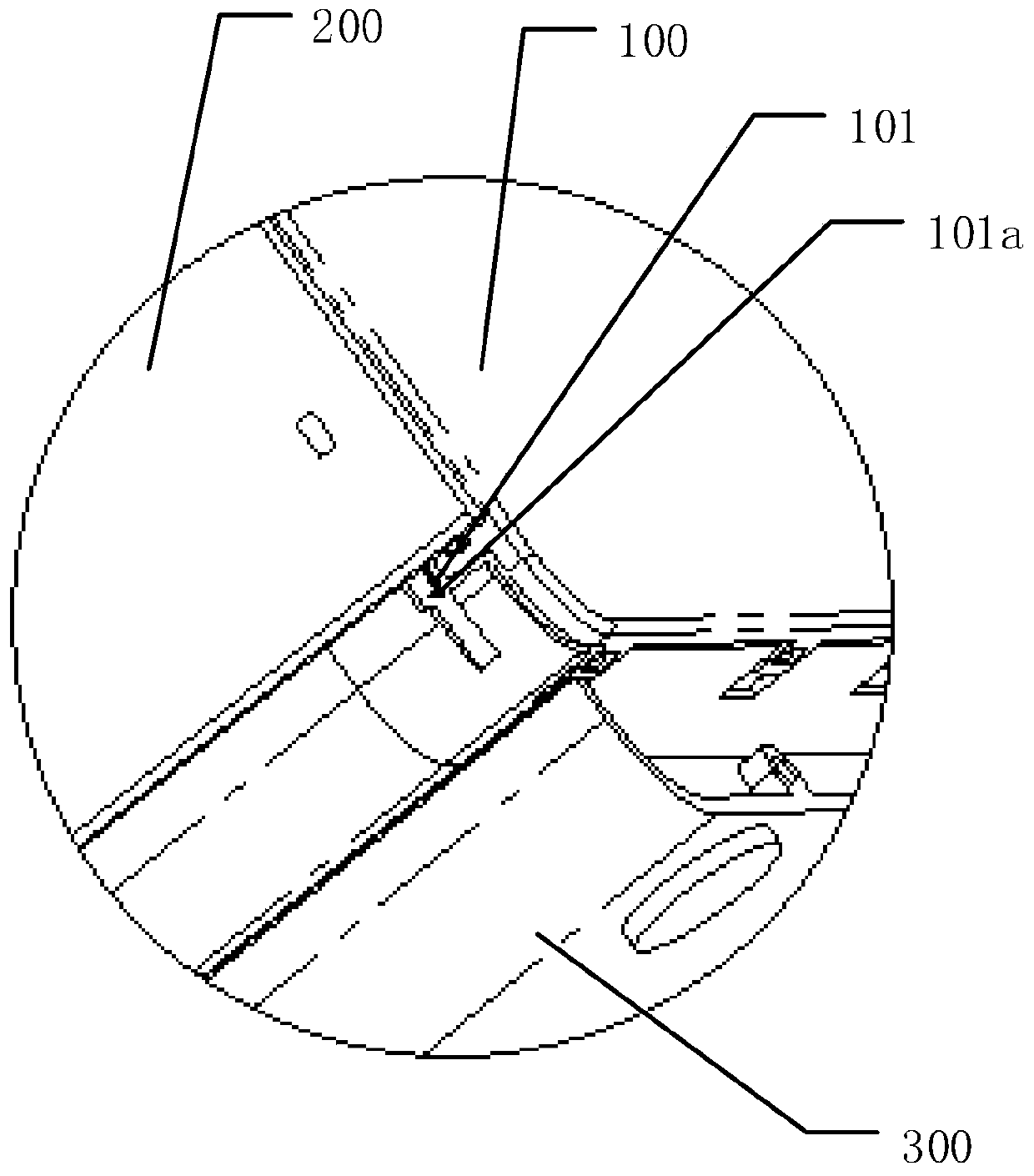
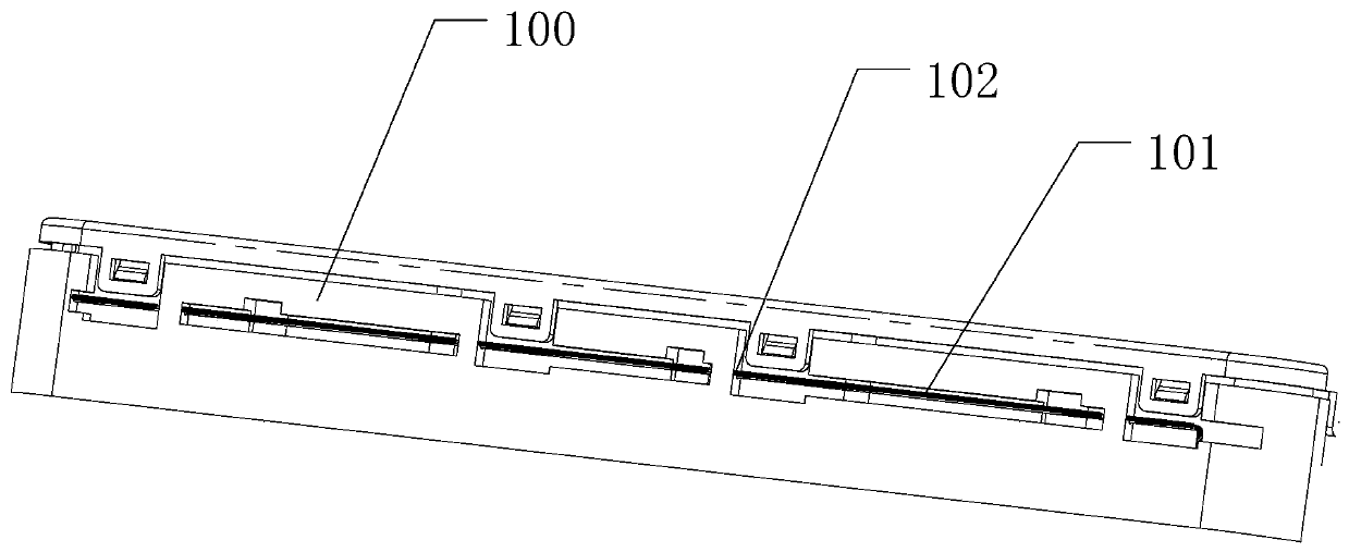
The invention discloses a shell structure of electronic equipment and electronic equipment. The electronic equipment comprises a main body; the shell structure comprises an appearance shell; the mainbody and the appearance shell are connected through a detachable connecting piece; the appearance shell comprises a U-shaped middle shell; the middle shell covers the top surface, left side surface and right side surface of the main body; and during disassembly, the detachable connecting piece is pulled out from the bottom of the electronic equipment, so that the main body is separated from the appearance shell. According to the shell structure and the electronic equipment of the invention, the main body of the electronic equipment is connected with the appearance shell through the detachableconnecting piece. When the electronic equipment is to be used, only the detachable connecting piece needs to be pulled out, so that the main body and the appearance shell can be quickly disassembled,and therefore, the electronic equipment is convenient use. The appearance shell comprises the U-shaped middle shell; and the disassembly position is arranged at the bottom of the electronic equipment,so that the disassembly position is more concealed, and therefore, the appearance of the electronic equipment can be effectively improved, and the use requirements of users are met. Compared with electronic equipment of which the plurality of screws need to be screwed from the outside, the electronic equipment of the invention is improved in appearance structure and can assist in saving manual operation cost.

Description

technical field [0001] The invention relates to a casing structure of an electronic device and the electronic device. Background technique [0002] Since the appearance of electronic devices such as speakers and TVs, they have brought more fun to people's lives. With the improvement of people's living standards, people's appreciation tastes have also been continuously improved, and the requirements for the appearance of these electronic devices are becoming more and more refined. and elegant. In the installation of traditional electronic equipment enclosures, the most commonly used connection method is screw connection. Although the screw connection is simple, standardized, and high in stability, the screws on the appearance destroy the overall shape of the electronic equipment, giving people a bad feeling. viewing experience. At the same time, the separate installation of multiple screws also requires more manual operations. Therefore, in today's rising labor costs, the i...

Claims


Application Information

Patent Timeline
Patent Type & Authority Applications(China)
IPC IPC(8): H05K5/02H05K5/03
CPCH05K5/0217H05K5/03
Inventor 周玉洁段其民
Owner GEER TECH CO LTD
Learn More