Invisible magnetic attraction structure and door
A magnetic suction and invisible technology, applied in the direction of building structure, building fastening devices, wing fan fastening devices, etc., can solve the problem that the sealing strip is difficult to achieve the ideal sealing effect, the installation process of the magnetic sealing strip is troublesome, and the light-colored door frame and door panel collocation and other issues, to achieve good sealing and sound insulation effect, improve convenience, convenient and quick installation.
- Summary
- Abstract
- Description
- Claims
- Application Information
AI Technical Summary
Problems solved by technology
Method used
Image
Examples
Embodiment 1
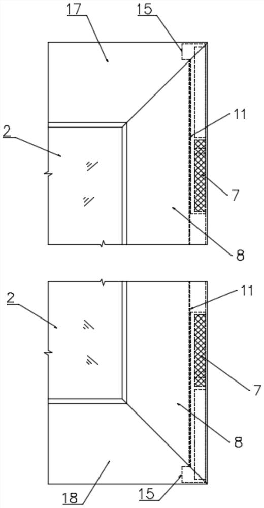
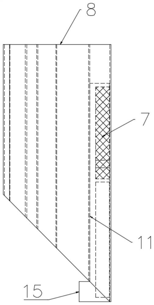
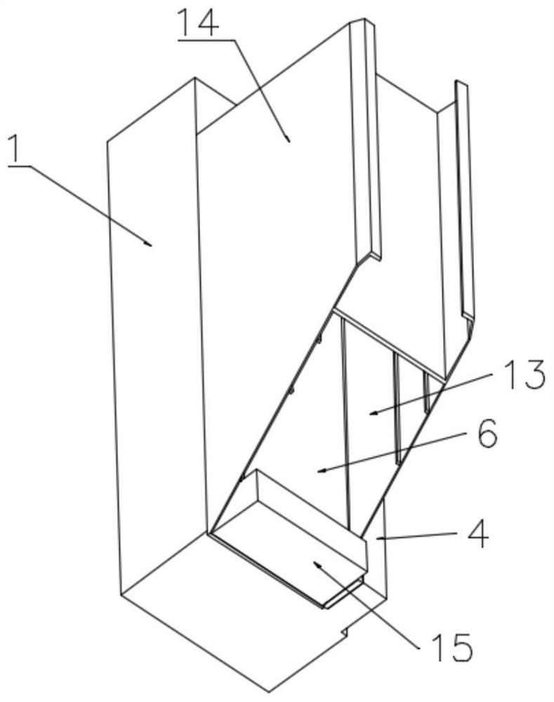
[0037] Such as Figure 1-Figure 8 As shown, this embodiment provides a hidden magnetic structure and door, including a magnetic adsorption assembly installed between the door frame 1 and the door panel 2, the magnetic adsorption assembly includes a first magnetic member 3 installed on the door frame 1 and a first magnetic member 3 installed on the door panel 2, the second magnetic part that is attracted to the first magnetic part 3, the door stopper 4 of the door frame 1 is provided with a sealing strip 5, and the first magnetic part 3 is installed between the sealing strip 5 and the door stopper 4; the second magnetic part Including the mounting seat 6 and the magnetic block 7, the mounting seat 6 is installed in the outer frame 8 of the door panel 2 and the mounting seat 6 corresponds to the position of the first magnetic part 3, and the magnetic block 7 is installed on the mounting seat 6 close to the first magnetic part 3 sides.
[0038] In this technical solution, since ...
Embodiment 2
[0040] This embodiment is optimized on the basis of the above-mentioned embodiment 1.
[0041] In order to achieve a better sealing and sound insulation effect, two magnetic sealing assemblies are arranged between the door frame 1 and the door panel 2 , and the two magnetic sealing assemblies are respectively arranged near the upper end and the lower end of the door panel 2 . That is to say, the two first magnetic parts 3 are respectively arranged on the doorstop 4 near the upper end and the lower end of the doorstop 4, and the two second magnetic parts are respectively arranged on the outer frame 8 opposite to the corresponding first magnetic parts 3. Location.
Embodiment 3
[0043] This embodiment is optimized on the basis of the above-mentioned embodiment 2.
[0044] In order to facilitate the unification of the structure of the mounting base 6 and to adapt to the installation on the upper and lower ends of the outer frame 8, the mounting base 6 is symmetrically provided with two mounting positions, which are respectively the first mounting position 9 and the second mounting position 10. The block 7 is installed at the first mounting position 9 or the second mounting position 10, and the mounting seat 6 is pushed into the outer frame 8 from the upper end or the lower end of the outer frame 8 respectively, and the first mounting seat 6 pushed in from the upper end of the outer frame 8 A magnetic block 7 is installed at the installation position 9, and a magnetic block 7 is installed at the second installation position 10 of the mounting seat 6 pushed in from the lower end of the outer frame 8 .
[0045] That is to say, regardless of whether the mo...
PUM
 Abstract
Description
Claims
Application Information
 - R&D
- Intellectual Property
- Life Sciences
- Materials
- Tech Scout
- Unparalleled Data Quality
- Higher Quality Content
- 60% Fewer Hallucinations
Browse by: Latest US Patents, China's latest patents, Technical Efficacy Thesaurus, Application Domain, Technology Topic, Popular Technical Reports.
© 2025 PatSnap. All rights reserved.Legal|Privacy policy|Modern Slavery Act Transparency Statement|Sitemap|About US| Contact US: help@patsnap.com


